Current sampling circuit and method

A current sampling and sampling current technology, applied in the direction of measuring current/voltage, measuring only current, electronic switches, etc., can solve the problems of large chip layout area overhead, unfavorable energy saving development trend, large chip layout area, etc., to achieve stable sampling The effect of current output, high degree of integration and simple structure

Active Publication Date: 2015-10-14
SANECHIPS TECH CO LTD
View PDF8 Cites 7 Cited by
  • Summary
  • Abstract
  • Description
  • Claims
  • Application Information

AI Technical Summary

Problems solved by technology

[0006] 1) In the above current sampling circuit, in order to provide the main gain of the closed-loop negative feedback circuit, it is necessary to add an error amplifier or adjustment tube to the clamp of the operational amplifier, so that the operational amplifier, error amplifier or adjustment The closed-loop negative feedback circuit composed of tubes occupies too much area of ​​the chip layout and requires a larger chip layout area. Therefore, the above-mentioned current sampling circuit is not conducive to the application in large-scale circuits with high integration;
[0007] 2) In the above-mentioned current sampling circuit, the bias currents I1 and I2 required by the closed-loop negative feedback circuit are large, reaching the ampere level or milliamp level. Therefore, the power consumption required by the above-mentioned current sampling circuit is large, which is not conducive to the current development trend of energy saving

Method used


Image

  • Current sampling circuit and method
  • Current sampling circuit and method
  • Current sampling circuit and method

Examples


Embodiment Construction

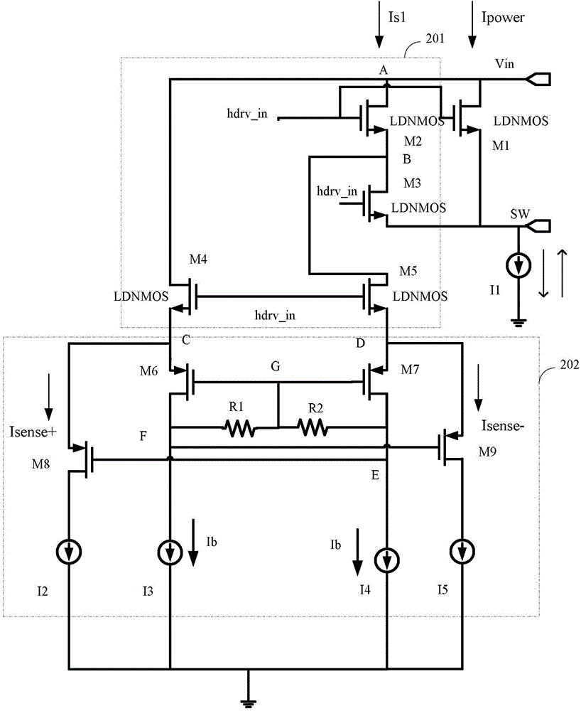
[0040] In the embodiment of the present invention, the current output by the power device is calculated according to the preset ratio to obtain the first proportional current and the second proportional current; a fully differential common-mode negative feedback circuit and a microampere-level bias current are used to control the first proportional current. The proportional current and the second proportional current are divided respectively to obtain the first sampling current and the second sampling current and output them constantly.

[0041] The specific embodiments of the present invention will be further described below in conjunction with the accompanying drawings.

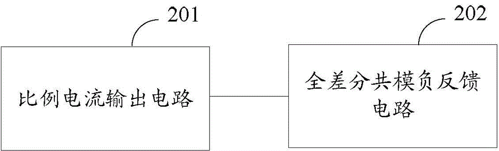
[0042] The embodiment of the present invention proposes a current sampling circuit for current sampling of power devices, such as figure 2 As shown, the current sampling circuit includes: a proportional current output circuit 201, a fully differential common-mode negative feedback circuit 202; wherein,

...


PUM


Abstract

A current sampling circuit and method, the current sampling circuit comprising a proportional current outputting circuit (201) and a fully differential common-mode negative feedback circuit (202); the proportional current output circuit (201) is used to calculate the current outputted by a power device based on a preset proportion, and obtain the first proportional current and the second proportional current for output to the fully differential common-mode negative feedback circuit (202); the fully differential common-mode negative feedback circuit (202)is used to shunt the first proportional current and the second proportional current by using a fully differential common-mode negative feedback network and the bias current of the microampere level, and obtain a first sampling current and a second sampling current for constant output.

Description

technical field [0001] The invention relates to a current sampling technology in the field of circuit design, in particular to a current sampling circuit and method. Background technique [0002] In the prior art, the realization method of forming a high-precision current sampling circuit is as follows figure 1 As shown, the current sampling circuit includes: power tube M1, sampling tubes M2 and M3, and a closed-loop negative feedback circuit composed of an operational amplifier, transistor M4, resistor R1, and resistor R2; where R1=R2, I1 and I2 are bias Setting current, the quiescent operating point of described closed-loop negative feedback circuit is provided, and the gain of described closed-loop negative feedback circuit is: [0003] A feedback =A op g m4 R o [0004] figure 1 The current sampling circuit shown first mirrors the current in the power tube M1 to the sampling tubes M2 and M3, and then passes through the closed-loop negative feedback circuit compose...

Claims


Application Information

Patent Timeline
Patent Type & Authority Applications(China)
IPC IPC(8): G01R19/00
CPCG01R19/0092H03K17/687G01R19/0038
Inventor 宋晓贞胡劼张永铂
Owner SANECHIPS TECH CO LTD
Why Eureka
Try Eureka