
System and method for estimating temperature of rotor of motor

一种转子温度、电动机的技术,应用在运动固体的温度测量、电动机参数的估测/修正、计算等方向,能够解决不能转子提供温度补偿控制、未教授估计转子温度等问题,达到提高性能和效率的效果

Inactive Publication Date: 2015-10-14
HYUNDAI MOTOR CO LTD
View PDF5 Cites 24 Cited by
  • Summary
  • Abstract
  • Description
  • Claims
  • Application Information

AI Technical Summary

Problems solved by technology

However, this known method does not teach estimating the temperature of the rotor, and thus may not provide proper temperature compensating control based on the temperature variation of the rotor

Method used


Image

  • System and method for estimating temperature of rotor of motor
  • System and method for estimating temperature of rotor of motor
  • System and method for estimating temperature of rotor of motor

Examples


Embodiment Construction

[0032] It should be understood that the term "vehicle" or "vehicular" or other similar terms as used herein includes motor vehicles in general, such as including sports utility vehicles (SUVs), buses, vans, various commercial vehicles Passenger vehicles, including boats and boats, watercraft, aircraft, etc., and includes hybrid vehicles, electric vehicles, plug-in hybrid electric vehicles, hydrogen vehicles and other alternative fuel vehicles (such as from fuel from sources other than petroleum). As referred to herein, a hybrid vehicle is a vehicle that has two or more sources of power, such as a vehicle that has both gasoline power and electric power.

[0033] Although the exemplary embodiment is described as using a plurality of units to perform the exemplary process, it should be understood that the exemplary process may also be performed by one or more modules. Additionally, it should be understood that the term controller / control unit refers to a hardware device includin...


PUM


Abstract

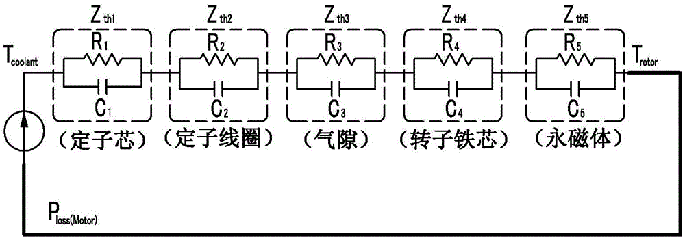
A system and method are provided for estimating temperature of a rotor of a motor configured to calculate temperature of the rotor using an actual measured data-based thermal model (thermal impedance model) and an energy loss model, and to estimate temperature of the rotor using the calculated temperature variation of the rotor. The method includes calculating, by a controller, an energy loss of the motor using driving conditions of the motor. The controller is also configured to calculate a temperature variation of the rotor in a predetermined reference temperature using the calculated energy loss and thermal resistances of the rotor and a stator of the motor. Further, the controller is configured to estimate a rotor temperature in the predetermined reference temperature using the temperature variation of the rotor.

Description

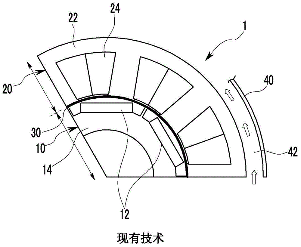
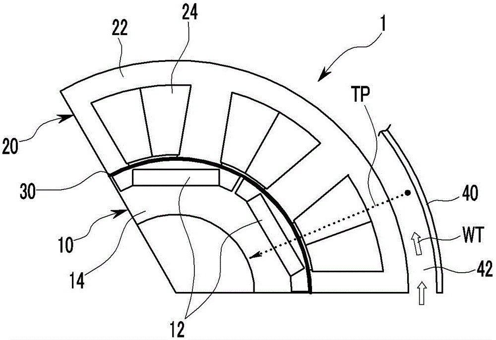
technical field [0001] The present invention relates to a system and method for estimating the rotor temperature of an electric motor, and more particularly to a method for calculating the temperature change of the rotor using a thermal model based on measured data (for example, a thermal resistance model) and an energy loss model, and then using the calculated rotor A system and method for estimating a rotor temperature of an electric motor. Background technique [0002] Generally, it is well known that an electric motor consists of a stator and a rotor. The stator refers to the fixed part in the motor, including the iron core that supports the current coils and the frame to which the iron core is mounted. The rotor is the rotatable part of an electric motor that includes permanent magnets and an iron core. figure 1 is an exemplary view showing a schematic structure of a drive motor used in an eco-friendly vehicle, in which an air gap is formed between a stator 20 and a r...

Claims


Application Information

Patent Timeline
Patent Type & Authority Applications(China)
IPC IPC(8): G06F19/00
CPCH02P23/14G01K13/08H02P23/0077
Inventor 金咏俊申政旼
Owner HYUNDAI MOTOR CO LTD
Learn More