Housing case flanger and use method thereof

A technology of flanging machine and blower, which is applied in the field of flanging machine, which can solve the problems of poor roundness accuracy, expensive equipment, and affecting fan performance, and achieve the effect of small assembly clearance and improved aerodynamic performance and efficiency

Active Publication Date: 2015-10-21
ZHEJIANG SHANGFENG SPECIAL BLOWER IND CO LTD
View PDF7 Cites 13 Cited by
  • Summary
  • Abstract
  • Description
  • Claims
  • Application Information

AI Technical Summary

Problems solved by technology

Initially, the flange side of the air duct was made by round butt welding of angle steel discs, and the bell mouth was made separately by molding, and then connected to the air duct, which not only wasted labor and materials, but also seriously affected the quality and appearance of the air duct
With the advancement of technology, the overall molding method is basically used to make the flange or bell mouth at the two ends of the air duct. One of them is processed by a digital display automatic flanging machine, and the quality of the flanging of the air duct is relatively low. Good, but the equipment is expensive; the other uses a relatively simple coreless flanging machine, which uses a roller to press the outer wall of the air cylinder in a circle, so that the end of the air cylinder is turned outward to form a flange or a bell mouth. There is no support on the inner wall of the air cylinder. The air cylinder made in this way has poor roundness accuracy. At the same time, the diameter of the two ends of the air cylinder will be slightly smaller than the diameter of the middle section of the air cylinder, resulting in a gap between the outer diameter of the impeller and the inner wall of the air cylinder. There is a large gap, which affects the performance of the fan

Method used


Image

  • Housing case flanger and use method thereof
  • Housing case flanger and use method thereof
  • Housing case flanger and use method thereof

Examples


Embodiment Construction

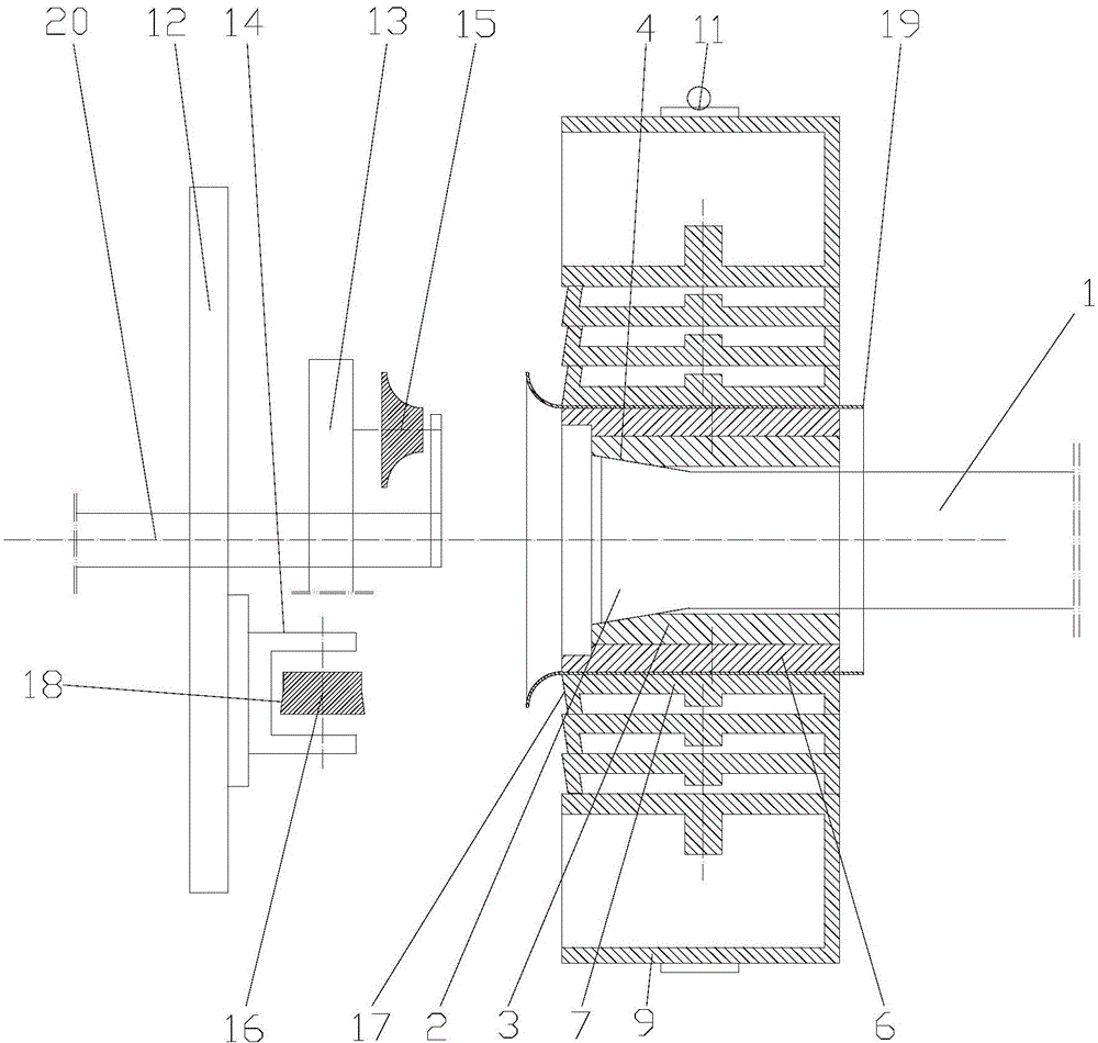
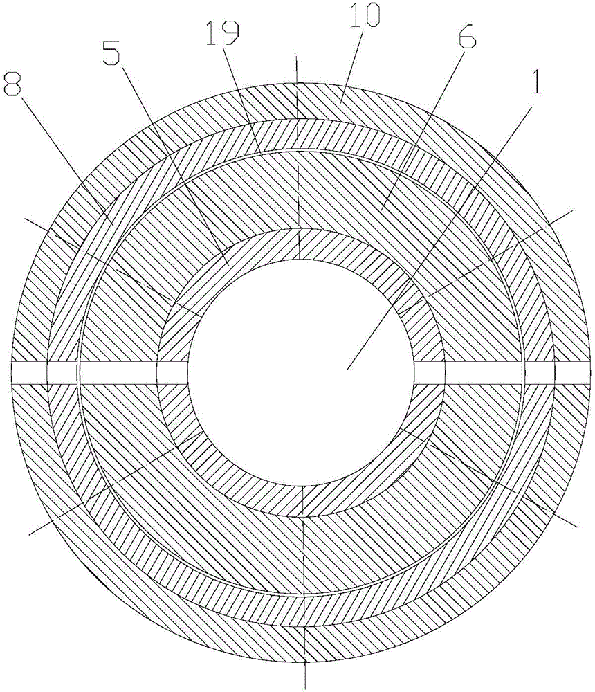
[0016] Such as figure 1 As shown, the present invention discloses a blower flanging machine, which includes an axial feed mechanism and a spindle box. In practical applications, the axial feed mechanism and the spindle box of the lathe can be utilized by refitting an existing ordinary lathe Box, the innovation point of the blower flanging machine according to the present invention is that it also includes a coaxially installed fixture device and a spinning device, the fixture device is fixed on the axial feed mechanism, and the spinning device The transmission is connected to the spindle box, and the spinning device can be driven to rotate axially through the spindle box. The fixture device includes a positioning shaft 1, and the end of the positioning shaft 1 facing one end of the spinning device has a truncated cone Body-shaped expansion chuck 2, the large end of the expansion chuck 2 faces the spinning device; the outer periphery of the positioning shaft 1 is provided with ...


PUM


Abstract

The invention discloses a housing case flanger, which comprises an axial feed mechanism, a main shaft box, a clamp device and a rotary pressing device, wherein the clamp device is fixed to the axial feed mechanism; and the rotary pressing device is in transmission connection with the main shaft box. The use method of the housing case flanger comprises the steps of fixing a housing case, rotary pressing a horn mouth, rotary pressing a right-angle side and the like. The housing case flanger and the use method thereof are adopted; through the autorotation of main rotating wheels and auxiliary rotating wheels and the rotation of a turnplate, a horn side and a right-angle side flange of the housing case are subjected to rotary pressing; since the clamp device which internally expands and externally holds is used for fixing the housing case, and the clamp device has an automatic centring rounding function, a necking-down phenomenon cannot happen to an opening of the housing case in the rotary pressing process, an assembling clearance between the impeller outer diameter of a draught fan which is finally assembled and the inner wall of the housing case can be reduced, and the aerodynamic performance and the efficiency of the draught fan are improved.

Description

technical field [0001] The invention relates to a flanging machine, in particular to a special flanging machine for making two-end flanges or bell mouths of an air duct and a method for using the flanging machine, belonging to the technical field of mechanical manufacturing equipment. Background technique [0002] The axial flow fan is mainly composed of a blower (casing), a motor and an impeller. The blower is cylindrical. To meet the needs of installation and air flow, the two ends of the blower are respectively provided with flanges or bell mouths. Initially, the flange side of the air duct was made by round butt welding of angle steel discs, and the bell mouth was made separately by molding and then connected to the air duct, which not only wasted labor and materials, but also seriously affected the quality and appearance of the air duct. With the advancement of technology, the overall molding method is basically used to make the flange or bell mouth at the two ends of t...

Claims


Application Information

Patent Timeline
Patent Type & Authority Applications(China)
IPC IPC(8): B21D19/06B21D22/14B21D43/00
Inventor 许宝华徐建锋
Owner ZHEJIANG SHANGFENG SPECIAL BLOWER IND CO LTD
Why Eureka
Try Eureka