
Operating method of buffer

A working method and buffer technology, applied in the direction of shock absorber, shock absorber, liquid shock absorber, etc., can solve the problem of sliding block rebound, relieve the pressure in the cavity, prolong the life of the shock absorber, and can be used in a wide range of places. Effect

Inactive Publication Date: 2015-10-21
蒋超
View PDF6 Cites 2 Cited by
  • Summary
  • Abstract
  • Description
  • Claims
  • Application Information

AI Technical Summary

Problems solved by technology

[0004] The technical problem to be solved by the present invention is to provide a working method of the buffer, which solves the technical problem that the slider rebounds when the slider hits the buffer

Method used


Image

  • Operating method of buffer
  • Operating method of buffer
  • Operating method of buffer

Examples


Embodiment 1

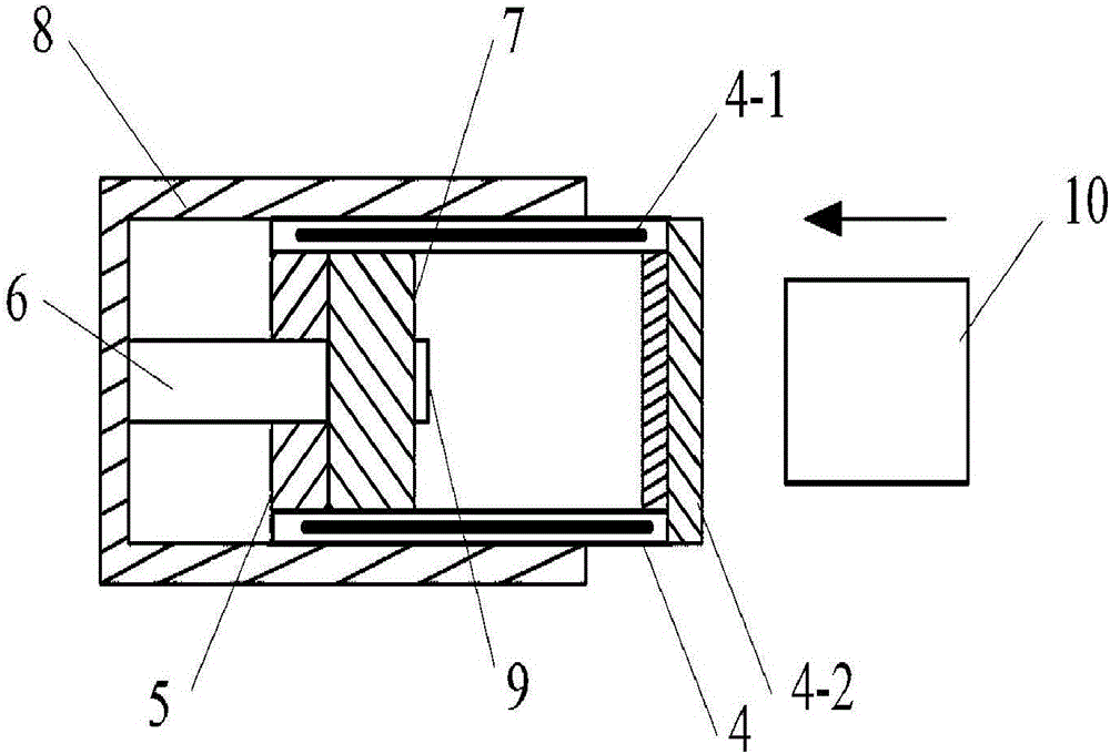
[0022] See figure 1 with Image 6 , a working method of a buffer, the buffer includes: a cylinder 4 that is cylindrical and used to fill a buffer medium, and a cylinder cover 5 is sealed at the open end of the cylinder 4, and the cylinder cover 5 A piston rod 6 is fitted in the center through hole of the seal movable, and the right end of the piston rod 6 is provided with a piston body assembly 7, and the piston body assembly 7 is suitable for piston movement in the cylinder body 4; the piston rod 6 The bottom is fixed to the left side of the outer cylinder 8 .

[0023] The working method of the buffer includes: during buffering work, the right end surface of the cylinder body 4 is used as a contact surface for colliding with the slider 10, and the right end surface is laid with a buffer pad 4 for buffering the impact of the slider 10- 2. An electromagnet 4-1 is arranged axially in the side wall of the cylinder body 4, and a pressure sensor 9 for detecting medium press...

Embodiment 2

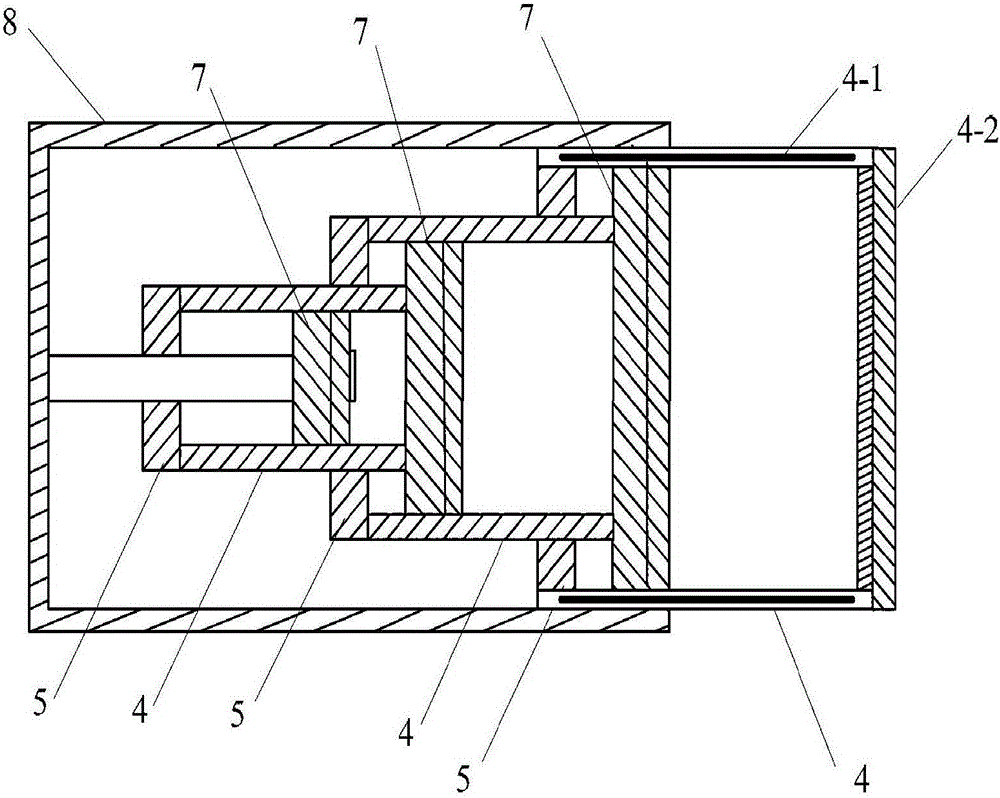
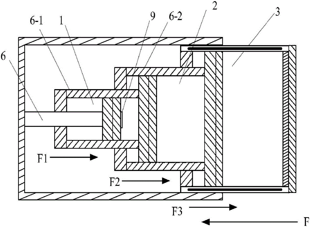
[0029] See figure 2 with image 3 , the buffer is a three-stage buffer, including: a first-stage buffer 1, an intermediate-stage buffer 2 and a final-stage buffer 3; the first-stage buffer 1, the intermediate-stage buffer, and the final-stage buffer 3 are respectively It includes: a cylinder body 4 that is cylindrical and used to fill with a buffer medium. A cylinder head 5 is sealed at the opening end of the cylinder body 4, and a piston rod 6 is sealed and movably fitted in the central through hole of the cylinder head 5. The right end of the piston rod 6 is provided with a piston body assembly 7, the piston body assembly 7 is suitable for piston movement in the cylinder body 4, and is movable and sealed with the inner wall of the cylinder body 4; wherein the first stage The cylinder 4 of the buffer 1 constitutes the piston rod 6-1 of the intermediate buffer 2, and the cylinder 4 of the intermediate buffer 2 constitutes the piston rod 6-2 of the final buffer 3; When...


PUM


Abstract

The invention relates to a working method of a buffer. The buffer comprises a cylinder body and a cylinder cover which seals an opening, wherein a central through hole is formed in a position of a central axis of the cylinder cover; a piston rod penetrates through the central through hole, a piston body component is arranged at the top of the piston rod, and a right side end surface of an outer cylinder is connected to the tail end of the piston rod; during buffering work, the right end surface of the cylinder body is taken as a contact surface colliding with the sliding block; an electromagnet is arranged axially in the side wall of the cylinder body, and a pressure sensor used for detecting the medium pressure is arranged on the right end surface of the cylinder body and connected with a processor module; when the sling block collides the right end surface of the cylinder body, the processor module is suitable for controlling a current driving module to output a current which is matched with a medium pressure value according to the medium pressure value, so that an electromagnet produces a corresponding magnetic field and attracts the sliding block; and until the medium pressure value measured by the processor module is an equilibrium value, the current driving module is controlled to close the output current, so that the sliding block is released.

Description

technical field [0001] The invention relates to a working method of a buffer, in particular to a working method of a buffer using elastic colloid as a buffer medium. Background technique [0002] In the field of cushioning and shock absorption, buffers are widely used, and their main functions are to absorb various impact energy, protect equipment and reduce noise. [0003] However, when the slider hits the buffer, due to the excessive impact energy, the piston in the buffer has no time to work, causing the slider to rebound. How to avoid this scene is a technical problem in this field. Contents of the invention [0004] The technical problem to be solved by the present invention is to provide a buffer working method, which solves the technical problem that the slider rebounds when the slider hits the buffer. [0005] The present invention provides a working method of a buffer, wherein the buffer includes: a cylindrical cylinder for filling with a buffer medium, a cylinde...

Claims


Application Information

Patent Timeline
Patent Type & Authority Applications(China)
IPC IPC(8): F16F9/22F16F9/34F16F9/32
CPCF16F9/22F16F9/30F16F9/303F16F9/32F16F9/3207F16F9/3214F16F9/3235F16F9/34F16F9/512
Inventor 不公告发明人
Owner 蒋超
Learn More