
Production method of microporous copper foil, microporous copper foil and production device thereof

A production method and microporous technology, applied in the direction of electrode carrier/collector, electrical components, electrolysis process, etc., can solve the problems of negative electrode material falling off, unsuitable copper foil, easy to be pulled and deformed, etc., to achieve appropriate thickness and not easy to fall off , not easy to break the effect

Inactive Publication Date: 2015-10-21
SHENZHEN XINYUREN TECH
View PDF3 Cites 16 Cited by
  • Summary
  • Abstract
  • Description
  • Claims
  • Application Information

AI Technical Summary

Problems solved by technology

The mesh-shaped copper foil is used for the negative electrode collector of lithium-ion batteries, and can connect the two reaction pools on both sides of the copper foil, but there are certain problems. On the one hand, due to the partial insulation treatment on the surface of the electrodeposition roller, Form dot-like graphics, which protrude from the surface of the electrodeposition roller, so that the copper foil is easily damaged when it is peeled off the surface of the electrodeposition roller; on the other hand, the microporous copper foil produced in this way has a mesh shape The mesh microporous copper foil is easy to be stretched and deformed when it is coated with a coating machine, so the copper foil is not suitable for coating with a coating machine, and the negative electrode material can only be attached to the Its surface, therefore, the negative electrode material is easy to fall off from the copper foil surface, affecting the use

Method used


Image

  • Production method of microporous copper foil, microporous copper foil and production device thereof
  • Production method of microporous copper foil, microporous copper foil and production device thereof
  • Production method of microporous copper foil, microporous copper foil and production device thereof

Examples


Embodiment Construction

[0024] In the description of the present invention, it should be understood that the orientation or positional relationship indicated by the terms "center", "upper", "lower", "front", "rear", "left", "right" etc. are based on The orientation or positional relationship shown in the drawings is only for the convenience of describing the present invention and simplifying the description, and does not indicate or imply that the referred device or element must have a specific orientation, be constructed and operated in a specific orientation, and therefore cannot be understood as Limitations on the Invention. In addition, the terms "first" and "second" are used for descriptive purposes only, and should not be understood as indicating or implying relative importance.

[0025] In the description of the present invention, it should be noted that unless otherwise specified and limited, the terms "installation", "connection" and "connection" should be understood in a broad sense, for e...


PUM


Abstract

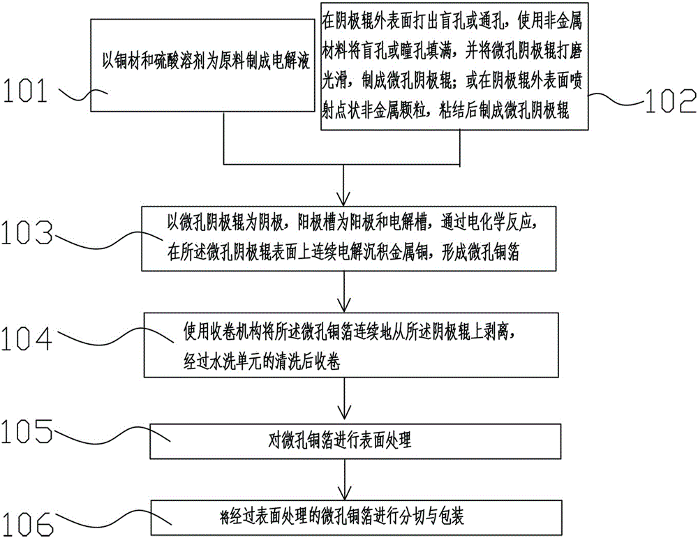
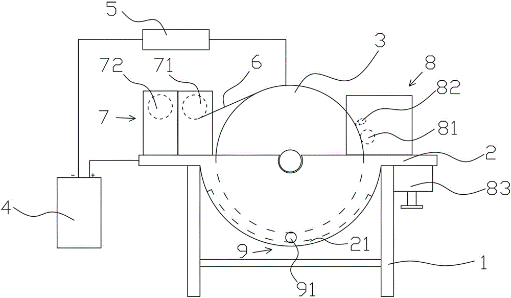
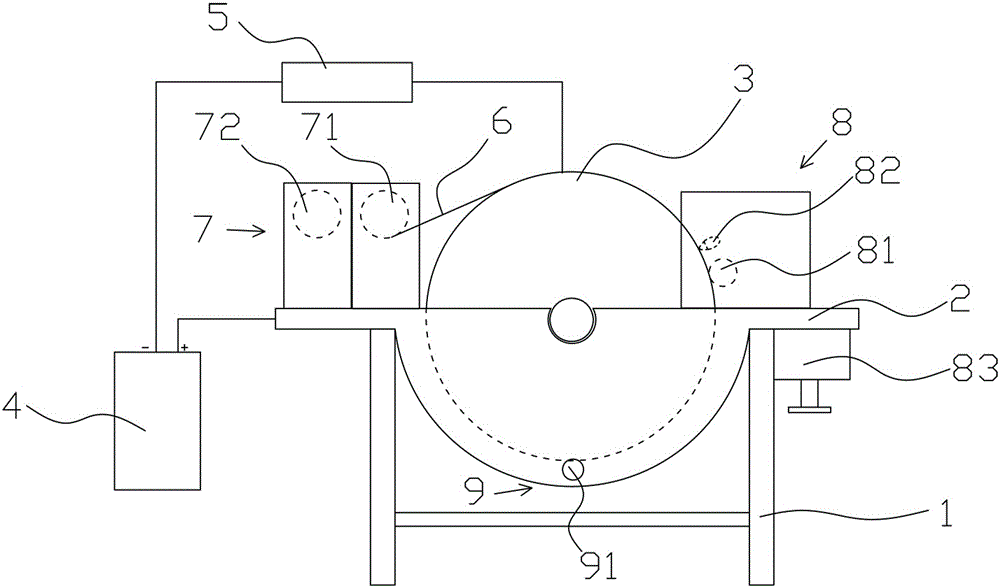
The invention provides a production method of a microporous copper foil, a microporous copper foil and a production device thereof. The production method comprises the following steps: taking a solution containing copper ions as an electrolyte, taking a prefabricated microporous cathode roll as a cathode, taking an anode cell as an anode, continuously electrolyzing depositing metal copper on the surface of the microporous cathode roll to form a microporous copper foil, wherein the microporous cathode roll is a cathode roll with a plurality of nonmetal dotted articles on a surface, contacting the electrolyte, of the cathode roll. The production device comprises a stander, wherein the stander is provided with the anode cell, the anode cell is connected with an anode of a power source by virtue of a copper bar, a cathode roll connected with a cathode of the power source is arranged above the anode cell, and the cathode roll is a microporous cathode roll. The microporous copper foil produced by adopting the production method is suitable for the smearing of a smearing machine, so that a cathode material is unlikely to drop; the microporous copper foil has advantages of being appropriate in thickness and not prone to deform and damage.

Description

technical field [0001] The invention relates to the field of electronic materials, in particular to a manufacturing method of a microporous copper foil applied to a lithium battery, a microporous copper foil and a manufacturing device thereof. Background technique [0002] Lithium-ion battery is a secondary technology widely used at present, which has the advantages of large capacity, small size and light weight. In existing lithium-ion batteries, copper foil is usually used as the current collector of the negative electrode, and the negative electrode material is coated on the surface of the copper foil to form a negative electrode; aluminum foil is used as the current collector of the positive electrode, and the positive electrode material is coated on the surface of the aluminum foil to form a positive electrode; The positive electrode and the negative electrode are separated by a separator and stacked to form a lithium-ion battery. [0003] At present, the most commonly...

Claims


Application Information

Patent Timeline
IPC IPC(8): H01M4/66H01M4/80C25D1/04
CPCC25D1/04H01M4/661H01M4/80Y02E60/10
Inventor 杨志明
Owner SHENZHEN XINYUREN TECH
Learn More