Infrared super enhanced collection antenna based on electromagnetically induced transparency

An electromagnetic induction transparent and infrared super technology, applied in the field of infrared detection, can solve problems such as photodetector performance degradation, and achieve the effects of increasing photoconductive gain, improving collection efficiency, and improving response rate

Inactive Publication Date: 2015-10-21
HUAZHONG UNIV OF SCI & TECH
View PDF3 Cites 2 Cited by
  • Summary
  • Abstract
  • Description
  • Claims
  • Application Information

AI Technical Summary

Problems solved by technology

[0004] Aiming at the defects of the prior art, the purpose of the present invention is to provide a transparent infrared super-enhanced collection antenna based on electromagnetic induction, aiming to solve the problem of photodetector performance degradation caused by the increase of the electrode spacing of infrared photon detectors in the prior art. Technical problems, and provide polarization-independent detection solutions

Method used


Image

  • Infrared super enhanced collection antenna based on electromagnetically induced transparency
  • Infrared super enhanced collection antenna based on electromagnetically induced transparency
  • Infrared super enhanced collection antenna based on electromagnetically induced transparency

Examples


preparation example Construction

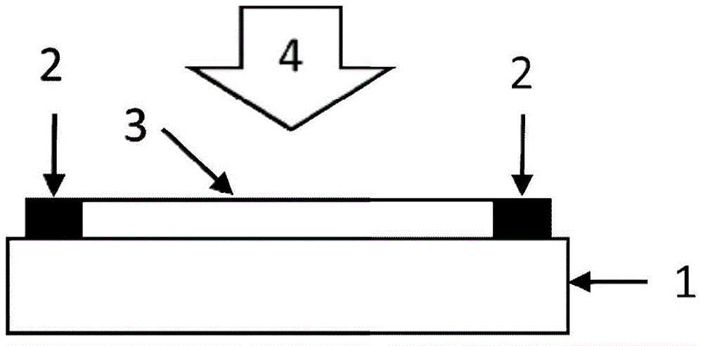
[0026] According to another aspect of the present invention, there is provided a method for preparing an infrared super-enhanced collection antenna based on electromagnetic induction transparency, comprising the following steps:

[0027] (1) Spin-coat negative photoresist on a substrate attached with a photosensitive material;

[0028] (2) Utilize an electron beam exposure machine to expose the negative photoresist, and make a sample based on electromagnetic induction transparent infrared super-enhanced collection antenna array and metal electrode pattern;

[0029] (3) developing the exposed sample;

[0030] (4) Use electron beam evaporation to deposit infrared super-enhanced collection antenna arrays and metal electrode materials based on electromagnetic induction transparency. The materials can be selected but not limited to nickel / titanium (adhesion layer) and gold / silver / copper / aluminum;

[0031] (5) After peeling off the photoresist, an infrared super-enhanced collection...

Embodiment 1

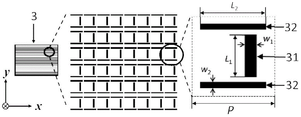
[0036] Such as image 3 As shown, the infrared super-enhanced collection antenna 3 based on electromagnetic induction transparency is an array of metal rods arranged periodically, wherein the horizontal direction is the x-axis direction, and the vertical direction is the y-axis direction. Each antenna unit in the array includes two kinds of resonant units, the first resonant unit 31 is placed along the y-axis, the second resonant unit 32 is two metal rods placed in parallel, and the first resonant unit 31 is placed in the second resonant unit 32. Between two metal rods, the direction is perpendicular to it. The antenna size is generally 1 / 10 to 1 / 5 of the design wavelength, so in the infrared band, the length L of the metal rod of the first resonant unit 1 and the metal rod length L of the second resonant unit 2 Range 0.5 micron ~ 5.0 micron, width w 1 and w 2 The range of P is 0.1 micron to 1.0 micron, and the range of P of the period is 0.6 micron to 5.5 micron. The mat...

Embodiment 2

[0039] Such as Figure 4 , the transparent infrared super-enhanced collection antenna 3 based on electromagnetic induction is an array of metal rods arranged periodically, wherein the horizontal direction is the x-axis direction, and the vertical direction is the y-axis direction. Each unit in the array includes two kinds of resonant units, the first resonant unit 31 is placed along the y-axis, the second resonant unit 32 is a metal rod placed along the x-axis, and the first resonant unit 31 is placed between the two second resonant units 32 , the direction is perpendicular thereto, and the first resonant unit 31 adjacent in the y direction is symmetrical to the center of the second resonant unit between them. The antenna size is generally 1 / 10 to 1 / 5 of the design wavelength. In the infrared band, the length L of the metal rod of the first resonant unit 1 and the metal rod length L of the second resonant unit 2 Range 0.5 micron ~ 5.0 micron, width w 1 and w 2 The range is...


PUM


Abstract

The invention provides an infrared super enhanced collection antenna based on electromagnetically induced transparency. The infrared super enhanced collection antenna includes a plurality of antenna units in periodical array distribution. Each antenna unit includes a first resonant unit and a second resonant unit, wherein the resonance frequency of the first resonant unit is identical or similar to that of the second resonance unit. Electromagnetically induced transparency in an infrared band is realized through the coupling effect of the first resonant unit and the second resonance unit, so that efficiency of collection of infrared radiation with target frequency is improved. By adopting the infrared super enhanced collection antenna, energy of incident polarized light can be distributed again and energy can be transferred to a direction perpendicular to the incident polarization direction, so that polarization conversion of incident electromagnetic waves is realized. At the moment, a local electric field formed at the frequency is distinctively greater than that formed due to direction excitation and polarization irrelevance detection at the target frequency is realized at the same time of realizing super enhanced collection.

Description

technical field [0001] The invention belongs to the technical field of infrared detection, and in particular relates to an infrared super-enhanced collection antenna based on electromagnetic induction transparency. Background technique [0002] For decades, under the traction and promotion of military applications, infrared photoelectric technology has developed rapidly. At present, this technology is developing in the direction of high-performance infrared detection. Designing various antenna structures is an effective way to improve the performance of infrared detectors. However, when developing high-performance infrared photonic antennas, the distance between the antenna electrodes will be further increased due to the increase of the working wavelength. Under the condition of constant carrier mobility, the increase of the distance between the electrodes will lead to the transition of photo-generated carriers in photosensitive materials. The prolongation of time, the reduc...

Claims


Application Information

Patent Timeline
Patent Type & Authority Applications(China)
IPC IPC(8): H01Q21/00
Inventor 陈长虹孟德佳李霄
Owner HUAZHONG UNIV OF SCI & TECH
Why Eureka
Try Eureka