
Digital constant current controller based on flyback primary side feedback

A primary-side feedback, constant-current control technology, which is applied in the direction of conversion equipment with intermediate conversion to AC, to achieve the effects of improving compensation accuracy, improving constant current accuracy and simple structure

Inactive Publication Date: 2015-10-21
SOUTHEAST UNIV
View PDF4 Cites 9 Cited by
  • Summary
  • Abstract
  • Description
  • Claims
  • Application Information

AI Technical Summary

Problems solved by technology

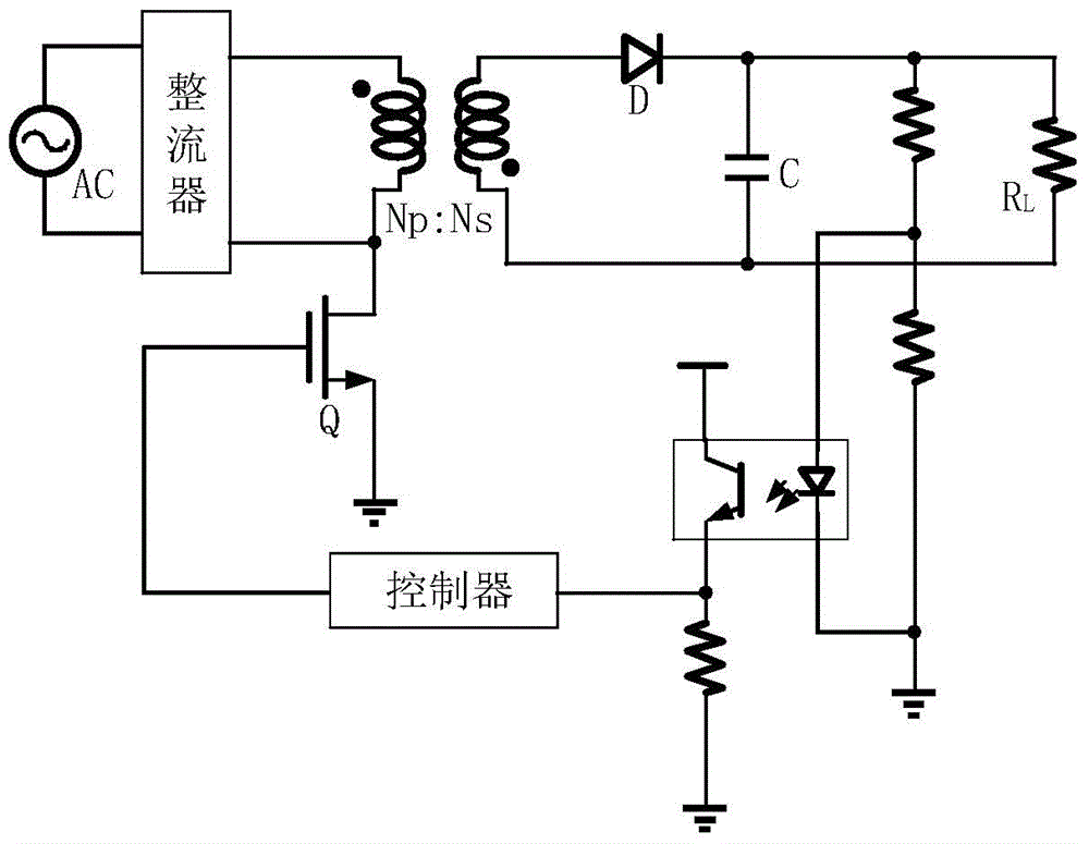
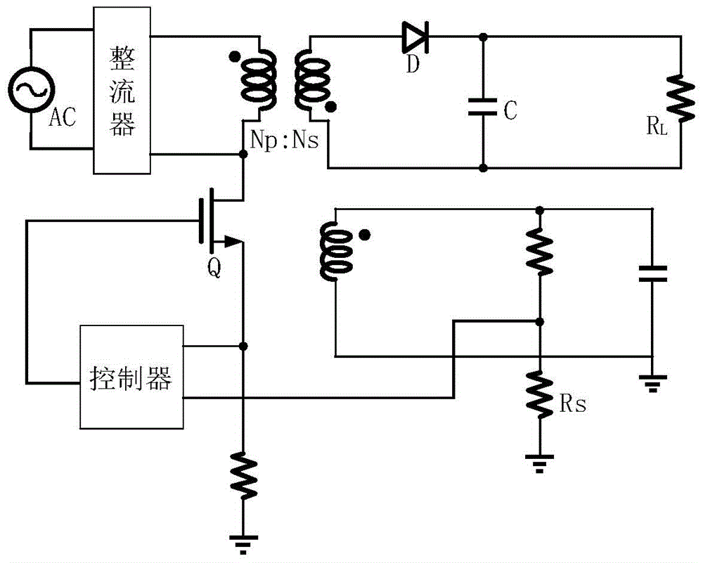
[0008] Aiming at the existing problems in the design of digitally controlled switching power supplies in the prior art, the present invention provides a digital constant current controller based on flyback primary side feedback. Through digital compensation technology, it solves the problem of the high-cost and high-performance ADC of the digital controller. reliance, reducing the cost of the controller

Method used


Image

  • Digital constant current controller based on flyback primary side feedback
  • Digital constant current controller based on flyback primary side feedback
  • Digital constant current controller based on flyback primary side feedback

Examples


Embodiment Construction

[0030] In order to describe the present invention in more detail, the specific implementation technical solutions and related principles of the present invention will be introduced and explained in detail below in conjunction with the accompanying drawings.

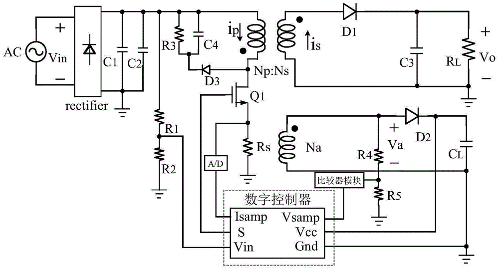
[0031] image 3 It is a digitally controlled flyback converter system, and the digital controller in the figure is the present invention. The invention is used in the flyback converter to control and regulate the constant current output of the flyback converter. In this flyback converter system, the current value of the primary side is sampled through a sampling resistor Rs, quantized by an 8-bit ADC, and then the sampling signal Isamp is transmitted to the digital controller. Divide the voltage on the auxiliary winding through the voltage dividing circuit, and compare the divided signal on the auxiliary winding with the 0V voltage through the comparison module to obtain a high and low level signal Vsamp, such as Figur...


PUM


Abstract

The invention provides a digital constant current controller based on flyback primary side feedback. The digital constant current controller comprises an auxiliary winding output voltage sampling state machine, a demagnetizing time Td compensation module, a bidirectional counter module, a primary side peak current Ip, pk(n) compensation module, a primary side peak current threshold value setting module and a switch signal control module. The digital constant current controller controls a flyback converter to enable the flyback converter to work in a discontinuous conduction mode (DCM), guarantees that the primary side peak value is constant in each switch period through frequency pulse modulation (PFM), and also guarantees that the ratio of the demagnetizing time to the switch period is constant so that digital constant current is realized. Based on the flexibility of digital control, the digital constant current controller provides demagnetizing time compensation and compensates for the delay of demagnetizing time sampling, thereby improving the constant current accuracy. A novel primary side peak value compensation method is provided for the delay in a flyback system, so that the primary side current compensation accuracy is improved and the linearity of output current is higher.

Description

technical field [0001] The invention relates to a switching power supply, in particular to a digital constant current controller based on flyback primary side feedback, which can be applied to charger constant current control and LED constant current drive. Background technique [0002] Due to the advantages of small size, low cost, and wide input voltage range, the flyback switching power supply is widely used in low-power devices, especially in chargers and LED drivers. The switching power supply with constant current output is mainly used for fast charging of chargers under low load conditions to improve energy utilization and work efficiency. In the field of LED driving, in order to increase the service life of LED lamps and improve the utilization rate of energy, a constant current is required for driving. [0003] The traditional flyback converter constant current control scheme mainly includes direct feedback on the output current from the output terminal to adjust i...

Claims


Application Information

Patent Timeline
Patent Type & Authority Applications(China)
IPC IPC(8): H02M3/28
Inventor 常昌远黄晓敏朱文文周中杰周志琪胡俊杰
Owner SOUTHEAST UNIV
Learn More