Quick starting circuit for charge pump phase-locked loop
A fast start-up and charge pump technology, applied in the automatic control of power, electrical components, etc., can solve the problem that the phase-locked loop cannot be locked quickly
- Summary
- Abstract
- Description
- Claims
- Application Information
AI Technical Summary
Problems solved by technology
Method used
Image
Examples
Embodiment Construction
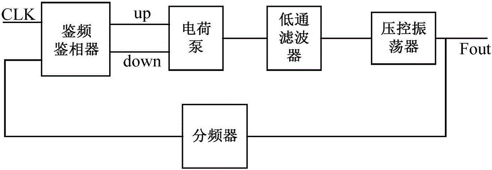
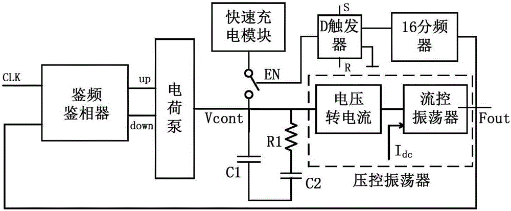
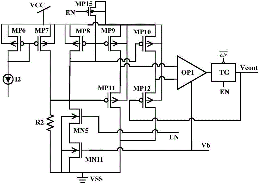
[0021] The present invention proposes a fast charging charge pump phase-locked loop, the specific circuit structure is as follows Figure 2-Figure 6 As shown, the specific connection relationship is as follows:
[0022] The input of the frequency and phase detector is the clock signal CLK and the output signal Fout of the flow control oscillator, and the output is two charge and discharge control signals up and down required by the charge pump.
[0023] The sources and substrates of MP1, MP3, MP15, and MP16 inside the charge pump and the substrates of MP2, MP4, and MP5 are connected to the power supply voltage, and the sources and substrates of MN2, MN3, and MN10 are connected to the substrates of MN1 and MN4. Potential, the drain of MP1 is connected to the source of MP2, the drain of MP15 is connected to the source of MP4, the drain of MP16 is connected to the source of MP5, the source of MN1 is connected to the drain of MN2, the source of MN4 is connected to the drain of MN1...
PUM
 Abstract
Description
Claims
Application Information
 - R&D
- Intellectual Property
- Life Sciences
- Materials
- Tech Scout
- Unparalleled Data Quality
- Higher Quality Content
- 60% Fewer Hallucinations
Browse by: Latest US Patents, China's latest patents, Technical Efficacy Thesaurus, Application Domain, Technology Topic, Popular Technical Reports.
© 2025 PatSnap. All rights reserved.Legal|Privacy policy|Modern Slavery Act Transparency Statement|Sitemap|About US| Contact US: help@patsnap.com


