
High temperature rotary lifting mechanism

A lifting mechanism and lifter technology, which is applied in the field of high-temperature rotary lifting mechanism, can solve the problems of lifting device paralysis, material falling, damage, etc., and achieve the effect of avoiding hidden troubles

Active Publication Date: 2017-10-10
浙江三基钢管有限公司
View PDF4 Cites 0 Cited by
  • Summary
  • Abstract
  • Description
  • Claims
  • Application Information

AI Technical Summary

Problems solved by technology

Although the output driving force of this multi-motor-driven lifting mechanism is relatively large, the main problem is that when one of the driving motors fails, the other driving motors are still working, so the lifting platform will inevitably occur. Tilting, which in turn leads to falling of materials and paralysis or damage of lifting devices
However, since the workpiece needs to be transported from one layer to another in the furnace, it is necessary to set up a lifting transmission mechanism at one end of the furnace.

Method used


Image

  • High temperature rotary lifting mechanism
  • High temperature rotary lifting mechanism

Examples


Embodiment 1

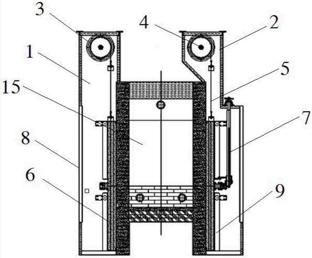
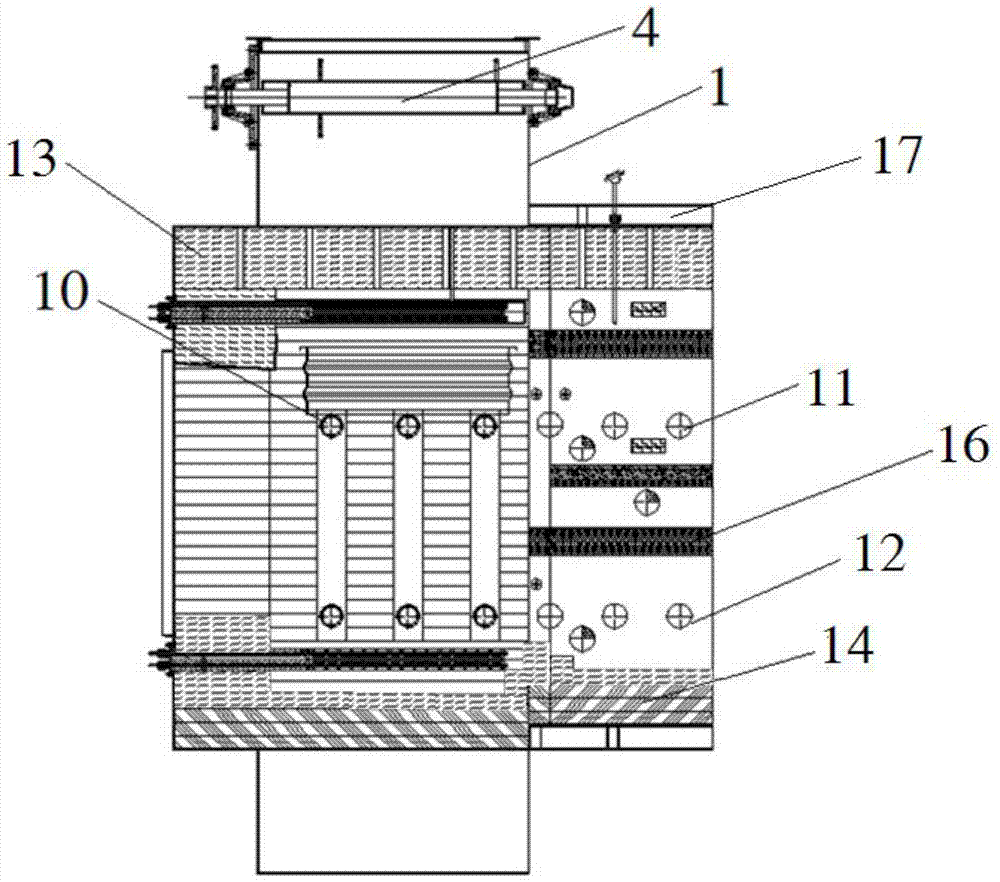
[0025] Embodiment 1: as Figures 1 to 2 As shown, the high-temperature rotary lifting mechanism described in Embodiment 1 includes a lifter 1 and a lifting area 15, and a plurality of heating elements, a plurality of thermocouples, and a plurality of cooling systems are arranged in the lifting area 15, and the lifting area 15 15 The top of the inner wall is provided with insulation material 13, and the bottom of the inner wall is provided with insulation material 13 and refractory insulation bricks 14 in turn. The elevator 1 includes a lifting device, and the lifting device includes a power output device. Shaft 4, each of the lifting rotating shafts 4 is arranged on two transmission sprockets 3, and the two lifting rotating shafts 4 are connected with the same power output device, and the four driving sprockets 3 are all connected by a chain 5 is connected with the lifting movable platform 6, and the two sides of the elevator 1 are provided with positioning wheels and slide ra...

Embodiment 2

[0028] Embodiment 2: as Figures 1 to 2As shown, the high-temperature rotary lifting mechanism described in Embodiment 2 is different from Embodiment 1 in that the elevator 1 includes a casing 2, and the casing 2 is provided with a maintenance door 8 and a maintenance manhole. An observation hole is arranged on the maintenance manhole.

Embodiment 3

[0029] Embodiment 3: as Figure 1 to Figure 2 As shown, the high-temperature rotary lifting mechanism described in Embodiment 3 is different from Embodiment 1 in that one side of the lifting area 15 communicates with the double-layer heat treatment furnace 17, and the inside of the double-layer heat treatment furnace 17 is There are upper transmission rollers 11, lower transmission rollers 12, multiple heat insulation layers 16, multiple heating elements, multiple cooling systems, and multiple thermocouples. The top of the furnace is provided with an insulating material 13, and the bottom of the furnace is sequentially provided with There are insulation materials 13 and refractory insulation bricks 14, and at least one circulation fan is provided on the furnace roof of the heat treatment furnace 17. Among them, the metal workpiece is transferred from one end of the furnace body to the other end of the furnace body through the upper transmission idler 11, and then the metal wor...


PUM


Abstract

The invention relates to a high-temperature rotary lifting mechanism. The lifting mechanism includes a lifting area and an elevator. The elevator includes a lifting device. The lifting device includes a power output device. There are two lifting rotating shafts on both sides of the top, and the two lifting rotating shafts are connected with the power output device. The driving sprockets are respectively arranged on the lifting rotating shafts, and the driving sprockets are connected to the lifting movable platform through a chain. connected with each other, the lifting movable frame is provided with a lifting movable frame, and a transmission device is provided on the lifting movable frame, and a plurality of transmission rollers are arranged on the transmission device, and the transmission device is connected with the driving motor. The high-temperature rotary lifting mechanism of the present invention has the advantages of being driven by a single power source for lifting, which can realize the up, down, left and right transmission of materials and the advantages of controllable temperature in the lifting area.

Description

technical field [0001] The invention relates to a lifting mechanism, in particular to a high-temperature rotary lifting mechanism with a single power source driving the lifting, a transmission device, and a controllable temperature in the lifting area and its application in a heat treatment furnace. Background technique [0002] Lifting mechanism is a kind of mechanical equipment or device widely used in industrial production that can carry people or goods on vertical up and down passages. At present, the existing types of lifting mechanisms generally include: scissor lifts, guide rail chain lifts, steel cable lifting devices, and screw lifting devices. Among them, scissor lifts are usually used in engineering because of their large overall structure and large size. For use in construction or industrial environments, its application threshold is relatively high and it is difficult to popularize. In addition, the existing guide rail chain type elevators, steel cable type lif...

Claims


Application Information

Patent Timeline
Patent Type & Authority Patents(China)
IPC IPC(8): C21D9/00F27D3/00
Inventor 来建良范本龙范本良王月琴王靖
Owner 浙江三基钢管有限公司
Learn More