Pit slot cleaning equipment and optimal parameter determination method

A technology for cleaning equipment and potholes, which is applied to roads, road repairs, roads, etc., can solve the problems of reduced bond strength, increased internal stress, and debris residue on the bonding surface, making it easy to carry and use, and improve bonding Effect, the effect of improving the repair life

Inactive Publication Date: 2015-10-28
蔡宜长 +1
View PDF7 Cites 4 Cited by
  • Summary
  • Abstract
  • Description
  • Claims
  • Application Information

AI Technical Summary

Problems solved by technology

Therefore, the repair interface of the pit is the most prone to secondary damage to the pit, and poor cleaning of the pit repair interface will cause a large amount of debris to remain in the pit, which will increase when the adhesive layer is arranged. The unevenness of the adhesive layer material, and the dust, debris and water on the repair interface will also reduce the bonding strength between the adhesive layer and the old asphalt surface. When the pothole repair interface is not well bonded, it will not only lead to The bond strength is reduced, and at the same time, the inhomogeneity of the bonding layer material will be increased, resulting in an increase in internal stress. Under these dual effects, the damage of the pit repair interface will be aggravated
[0004] At present, the pit cleaning technology adopted at home and abroad is generally compressed air or hot air blowing, manual tool cleaning, etc., although the pit cleaning process has been summarized in detail abroad, including blower blowing, high-pressure air blowing , high-temperature hot air injection, wire brush cleaning and other methods, and related cleaning equipment was proposed, but there are many types of processes, and there is no integrated research, and most of the test evaluations involved are subjective observations, lacking objective Evaluation test, it is difficult to clearly understand the specific impact of poor cleaning on the bonding performance of the pit repair interface

Method used


Image

  • Pit slot cleaning equipment and optimal parameter determination method
  • Pit slot cleaning equipment and optimal parameter determination method
  • Pit slot cleaning equipment and optimal parameter determination method

Examples


Embodiment Construction

[0048] Below in conjunction with accompanying drawing, the present invention is described in further detail:

[0049] 1. Equipment part

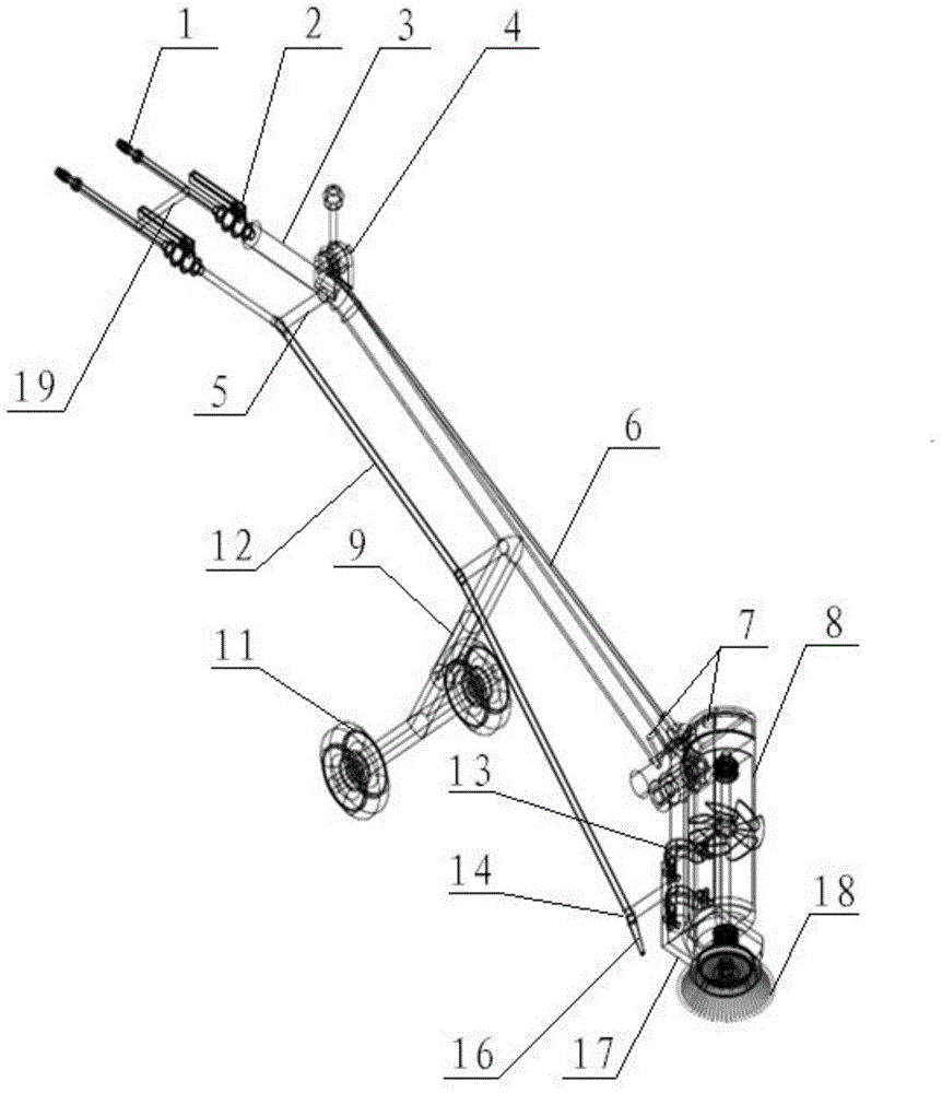
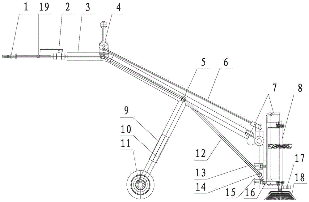
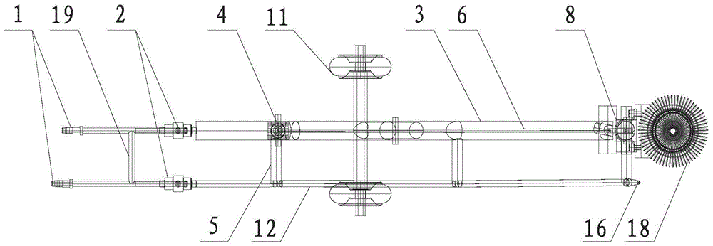
[0050] see Figure 1 to Figure 8 , the pothole cleaning equipment of the present invention mainly uses the rotating steel wire brush head quota and the high-pressure air spray gun to clean the dust and gravel on the pothole repair interface and remove the loose surface on the repair interface, and at the same time remove the water stains on the repair interface , to achieve the purpose of providing a clean, dry pit repair interface with good contact conditions. This equipment has an air motor 8 driven by high-pressure air to rotate. The air pipe and the air motor 8 are connected together through the air pipe interface 7 respectively arranged on the two, and the air motor 8 drives the cleaning brush head 18 to clean the pits. The purpose of patching the interface. Each part of the equipment is a modular independent part, which can be repla...


PUM


Abstract

The invention discloses pit slot cleaning equipment and an optimal parameter determination method. The pit slot cleaning equipment comprises a support pipe, a gas pipe is sleeved by the support pipe, one end of the gas pipe is connected to a high pressure air feeder, the other end of the gas pipe is connected to an air motor driven by high pressure air, the air motor is connected to the support pipe, the lower part of the air motor is provided with a cleaning brush head for cleaning a pit slot, and the middle of the support pipe is connected to a wheel shaft assembly for moving the pit slot cleaning equipment. The pit slot cleaning equipment can remove dust and broken stone on a pit slot repair interface, remove loose parts of the repair interface and remove water stains on the repair interface thereby providing a clean and dry pit slot repair interface with good contact conditions.

Description

technical field [0001] The invention belongs to the field of road surface pothole cleaning, and in particular relates to a pothole cleaning device and a method for determining optimal parameters thereof. Background technique [0002] At present, the effect of pothole repair is not good, some even repair in winter, and the spring is bad. In the Hubei section of Beijing-Zhuhai Expressway, the repair rate of potholes reached nearly 30% in the past 2005-10 years. Sha Qinglin found that even if the potholes are repaired in time, some road sections still need to be repaired for the second time within 1 to 2 months. For example, the No. 3 Expressway repaired in the winter at the end of 1998, the ratio of the second repair reached 12.8 %; Chen Dianqiang conducted a survey on road diseases in Anqiu City, Shandong Province in 2011, and found that potholes accounted for a relatively large proportion of the total road surface diseases, and the repair rate still reached 9.7% after recon...

Claims


Application Information

Patent Timeline
Patent Type & Authority Applications(China)
IPC IPC(8): E01C23/09
Inventor 蔡宜长周博闻惠冰
Owner 蔡宜长
Why Eureka
Try Eureka