
Optical network terminal apparatus having highlight protection function and method

An optical network terminal and protection function technology, applied in the field of communication, can solve the problems of large optical path and the protection function of the circuit that cannot be boosted, and achieve the effects of improving reliability, avoiding breakdown damage and wide application range.

Inactive Publication Date: 2015-10-28
SHANGHAI GONGJIN COMM TECH
View PDF11 Cites 0 Cited by
  • Summary
  • Abstract
  • Description
  • Claims
  • Application Information

AI Technical Summary

Problems solved by technology

It is protected by connecting a resistor in series on the high-voltage output line of the booster circuit (APD). The general resistance is selected as 5.1kohm. increase, so as to protect the light receiving component, but the actual test shows that the voltage drop of the 5.1kohm series resistor cannot protect the booster circuit (APD), but if the resistance continues to increase, although it can further reduce the Pressure effect, but too much resistance will affect the normal receiving overload of the optical path

Method used


Image

  • Optical network terminal apparatus having highlight protection function and method
  • Optical network terminal apparatus having highlight protection function and method
  • Optical network terminal apparatus having highlight protection function and method

Examples


Embodiment Construction

[0026] In order to describe the technical content of the present invention more clearly, further description will be given below in conjunction with specific embodiments.

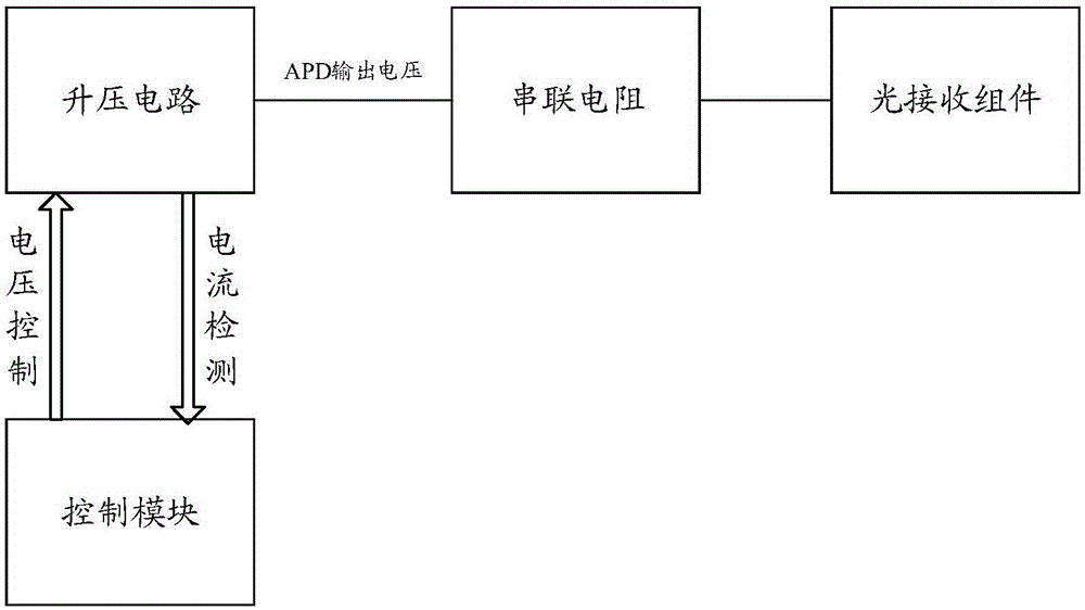
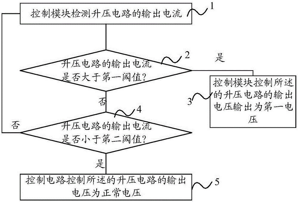
[0027] see Figure 2 to Figure 3 As shown, the optical network terminal device and method with strong light protection function of the present invention protect the device based on a combination of hardware and software. The optical network terminal device with strong light protection function of the present invention includes a boost circuit, a series resistor, a light receiving component and a control circuit, and the boost circuit is connected to the series resistor and the control circuit respectively, The series resistor is connected to the light-receiving component; the control circuit is used to detect the output current of the boost circuit, and when the output current of the boost circuit is greater than a first threshold, The control circuit controls the output voltage of the boost circuit to be ...


PUM


Abstract

The present invention relates to an optical network terminal apparatus having a highlight protection function, comprising a boost circuit, a series resistor, an optical receiving assembly and a control circuit; wherein the boost circuit is connected with the series resistor and the control circuit, the series resistor is connected with the optical receiving assembly; the control circuit is used for detecting an output current of the boost circuit, and when the output current of the boost circuit is greater than a first threshold value, the control circuit controls an output voltage of the boost circuit to be a first voltage, when the output current of the boost circuit is less than a second threshold value, the control circuit controls the output voltage of the boost circuit to be a normal voltage. The present invention also relates to a method for achieving the highlight protection function of the optical network terminal apparatus. According to the optical network terminal apparatus having the highlight protection function with the above structure and the method, the problem of breakdown and damage of the optical receiving assembly in a photoelectric conversion apparatus during input of highlight can be avoided, normal reception cannot be affected, reliability of the apparatus is further improved, and wide application range is achieved.

Description

technical field [0001] The present invention relates to the field of communication technology, in particular to optical communication technology, and specifically refers to an optical network terminal device and method with strong light protection function. Background technique [0002] Passive Optical Network technology PON (Passive Optical Network: Passive Optical Network) is a point-to-multipoint optical access technology. The transmission medium has the integrated service access function of data, voice and video. Passive optical network means that ODN (Optical Distribution Network: optical distribution network) does not contain any electronic devices and electronic power supplies. ODN is composed of passive devices such as optical splitters (Splitter) and does not require expensive active electronics. equipment. A passive optical network includes an optical line terminal (OLT) installed in a central control station, and a batch of supporting optical network units (ONUs...

Claims


Application Information

Patent Timeline
IPC IPC(8): H04B10/69H04Q11/00
Inventor 仵允贤袁德方
Owner SHANGHAI GONGJIN COMM TECH
Learn More