Optical module with blaze protection function
A protection function and optical module technology, applied in the field of optical communication, can solve the problems affecting the normal operation of passive optical network systems, economic losses of network managers and customers, breakdown and damage of optical receiving components, etc., to simplify maintenance work, reduce Maintenance cost, the effect of reducing the number of use
- Summary
- Abstract
- Description
- Claims
- Application Information
AI Technical Summary
Problems solved by technology
Method used
Image
Examples
Embodiment 1
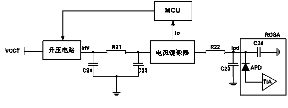
[0022] Embodiment 1. In this embodiment, in order to solve the problem that the receiving end of the optical module is easily broken down and damaged when the receiving end of the optical module is input by strong light, a high-voltage protection circuit is designed on the receiving end of the optical module. See figure 1 As shown, it is mainly composed of boost circuit, current mirror, current limiting resistor R22 and MCU. Among them, the input terminal of the boost circuit is connected to the DC power supply VCCT, and after the DC power supply VCCT is boosted and converted, the output high voltage HV is transmitted to the current mirror, and the high voltage output by the current mirror is transmitted to the optical receiver through the series current limiting resistor R22 Response current output of component ROSA. An avalanche photodiode APD and a transimpedance amplifier TIA are packaged in the light receiving component ROSA. The light receiving component ROSA receives th...
PUM
 Abstract
Description
Claims
Application Information
 - R&D
- Intellectual Property
- Life Sciences
- Materials
- Tech Scout
- Unparalleled Data Quality
- Higher Quality Content
- 60% Fewer Hallucinations
Browse by: Latest US Patents, China's latest patents, Technical Efficacy Thesaurus, Application Domain, Technology Topic, Popular Technical Reports.
© 2025 PatSnap. All rights reserved.Legal|Privacy policy|Modern Slavery Act Transparency Statement|Sitemap|About US| Contact US: help@patsnap.com


