
Battery piece bonding detection method

A detection method and cell technology, applied in sorting and other directions, can solve the problems of cell sticking, affecting continuity, production line blockage, etc., and achieving the effect of reasonable structure, small size and convenient control.

Inactive Publication Date: 2015-11-04
武汉中导光电设备有限公司
View PDF8 Cites 6 Cited by
  • Summary
  • Abstract
  • Description
  • Claims
  • Application Information

AI Technical Summary

Problems solved by technology

[0003] The purpose of the present invention is to provide a detection method for cell sticking, so as to solve the problem that the cell is prone to sticking during the production of existing solar cells. If it is not found and eliminated in time, it will lead to production line blockage, battery damage and other phenomena. , affecting the continuity of production and other technical issues

Method used


Image

  • Battery piece bonding detection method
  • Battery piece bonding detection method
  • Battery piece bonding detection method

Examples


Embodiment 1

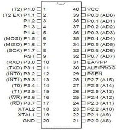
[0033] In embodiment 1, the controller selects the AT89S52 single-chip microcomputer of ATMEL Company.

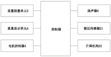
[0034] image 3 It is a schematic diagram of the single-chip microcomputer selected in Embodiment 1 of the present invention, Figure 4 is a schematic diagram of the weight measuring unit in Embodiment 1 of the present invention, Figure 5 It is a schematic diagram of the weight display unit in Embodiment 1 of the present invention, Figure 6 is a schematic diagram of the motor controller in Embodiment 1 of the present invention, Figure 7 is a schematic diagram of the speaker in Embodiment 1 of the present invention.

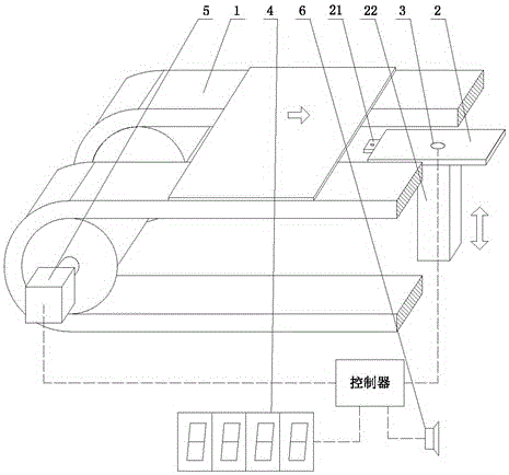
[0035] It can be seen from the figure that a pallet 2 is installed near the conveyor belt 1, a proximity sensor 21 is provided on the edge of the pallet 2, a weight detection unit 3 is provided in the center of the pallet 2, and a lifting mechanism 22 is provided at the bottom of the pallet 2; a weight display unit is also provided near the conveyor belt ...

Embodiment 2

[0043] The controller in embodiment 2 selects Mitsubishi FX2N series PLC.

[0044] PLC does not require complex line connections, because it has internal functions such as storing programs, executing logic operations, sequence control, timing, and counting, and only needs to determine input points and output points and perform logic programming.

[0045] In Embodiment 2, relay input and relay output can be set for each component. For example, the proximity sensor is defined as X1, the weight detection unit is set as X2, the lifting mechanism is set as Y1, the weight display unit is set as Y2, and the motor The controller is set to Y3 and the speaker is set to Y4.

[0046] By programming or drawing a ladder diagram, it is set that when the proximity sensor X1 has an input, the lifting mechanism Y1 has an output; when the weight detection unit X2 has an input, the weight display unit Y2 has an output, and according to the measurement result of the weight detection unit, the lift...


PUM


Abstract

The invention discloses a battery piece bonding detection method. The weight of a battery piece on a conveying belt is detected to judge if the weight is in a specification range of single battery piece to judge piece break and bad piece bonding so as to prevent defective products from entering subsequent stations. The battery piece bonding detection method has such advantages as reasonable structure and convenience for control. A traditional conveying belt is improved to realize the bonding detection of the battery piece and to timely remind operators to prevent the bad bonding piece from entering the subsequent procedures so as to cause bad consequences of production line blockage or piece break. The battery piece bonding detection method can preferably improve the battery piece bonding phenomenon in a traditional process, and is excellent in practical value.

Description

technical field [0001] The invention relates to a detection method for cell sticking in the photovoltaic industry. Background technique [0002] The production process of solar cells is to make thin silicon wafers cut out of silicon ingots into solar cells through a series of processes such as cleaning, texturing, doping, coating, screen printing, and sintering. In such a production process, the production and testing equipment needs to carry out the steps of loading, transporting, and unloading silicon wafers or cells many times, such as the cell printing equipment and IV sorting equipment of Applied Materials in the United States, and the Hennecke of Germany. Wafer testing and sorting machine, the silicon wafer testing and sorting machine of Semilab in Hungary, etc. These devices generally use robots to grab stacked silicon wafers or cells from the magazine and place them on the conveyor belt, and then go through a series of production or testing processes before distribu...

Claims


Application Information

Patent Timeline
Patent Type & Authority Applications(China)
IPC IPC(8): B07C5/16
Inventor 赵润川李波
Owner 武汉中导光电设备有限公司
Learn More