
Automatic hot melting device

A hot-melt and automatic technology, applied in welding equipment, metal processing equipment, electric heating devices, etc., can solve the problems of low operating efficiency, difficult hot-melt, poor hot-melt precision, etc., and achieve the effect of simple structure and convenient use

Inactive Publication Date: 2015-11-04
SUZHOU SECOTE PRECISION ELECTRONICS CO LTD
View PDF6 Cites 8 Cited by
  • Summary
  • Abstract
  • Description
  • Claims
  • Application Information

AI Technical Summary

Problems solved by technology

The current hot-melt mechanism is produced by manual work, so it has problems such as poor hot-melt precision, difficult hot-melt, and low operating efficiency.

Method used


Image

  • Automatic hot melting device

Examples


Embodiment Construction

[0013] The present invention will be further described below in conjunction with accompanying drawing.

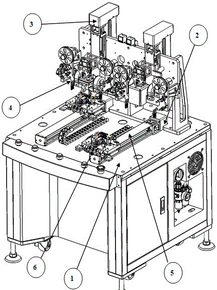
[0014] Automatic hot-melt equipment, including frame 1, X-axis module 2, Z-axis module 3, hot-melt mechanism 4, Y-axis module 5, cable positioning carrier 6, characterized in that X-axis module 2, Y-axis The axis module 5 is set on the frame 1, the Z-axis module 3 is set on the side of the Y-axis module 5 close to the X-axis module 2, the hot-melt mechanism 4 is set on the Z-axis module 3, and the cable positioning load The tool 6 is arranged on the Y-axis module 5 . There are two Y-axis modules 5 and two Z-axis modules 3, and the two Y-axis modules 5 are arranged side by side. The electrical circuits of the X-axis module 2 , the Z-axis module 3 , the hot-melt mechanism 4 , and the Y-axis module 5 are all arranged in the frame 1 . The cable positioning carrier 6 is positioned by a vacuum suction method of a stainless steel plate.

[0015] In actual use, put the product o...


PUM


Abstract

The invention relates to an automatic hot melting device. The automatic hot melting device comprises a machine frame, X-axis modules, Z-axis modules, hot melting mechanisms, Y-axis modules and flexible printed circuit positioning carriers, and is characterized in that the X-axis modules and the Y-axis modules are arranged on the machine frame; the Z-axis modules are arranged on the sides, close to the X-axis modules, of the Y-axis modules; the hot melting mechanisms are arranged on the Z-axis modules; and the flexible printed circuit positioning carriers are arranged on the Y-axis modules. In practical use, products are placed on the flexible printed circuit positioning carriers, the Y-axis modules drive the flexible printed circuit positioning carriers to move to the positions under the hot melting mechanisms, and then the Z-axis modules drive the hot melting mechanisms to move downwards to complete the hot melting action. Due to the fact that double stations alternately work and do not influence each other, the hot melting efficiency is improved. The automatic hot melting device can be connected with an appropriate single-chip microcomputer of electrical circuits of the X-axis modules, the Z-axis modules, the hot melting mechanisms and the Y-axis modules arranged in the machine frame, the pure automatic operation is achieved, and the hot melting pressure, the hot melting temperature and the hot melting time can be regulated at any time according to requirements of clients.

Description

technical field [0001] The invention relates to the field of mechanical manufacturing, in particular to automatic hot-melt equipment. Background technique [0002] Electronic technology is an emerging technology developed at the end of the nineteenth century and the beginning of the twentieth century. It developed the fastest and was most widely used in the twentieth century, becoming an important symbol of the development of modern science and technology. [0003] The first generation of electronic products centered on the electron tube. At the end of the 1940s, the first semiconductor triode was born in the world. With the characteristics of small size, light weight, power saving, and long life, it was quickly used by various countries and replaced electronic tubes in a large range. In the late 1950s, the first integrated circuit appeared in the world, which integrated many transistors and other electronic components on a silicon chip, making electronic products more mini...

Claims


Application Information

Patent Timeline
Patent Type & Authority Applications(China)
IPC IPC(8): B23K3/047
CPCB23K3/047B23K2101/36
Inventor 孙丰
Owner SUZHOU SECOTE PRECISION ELECTRONICS CO LTD
Learn More