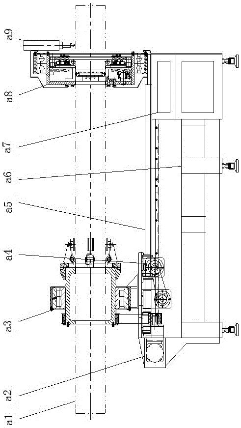
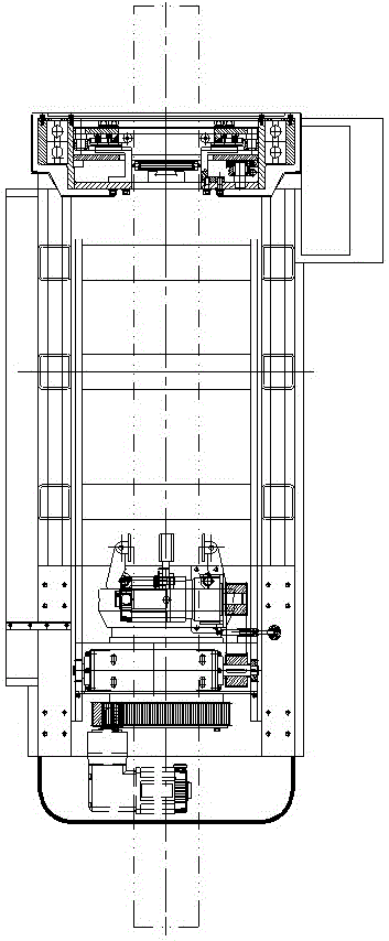
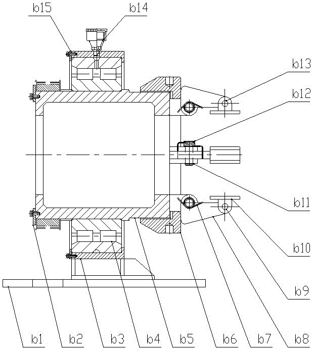
Rotary chuck and laser pipe cutting machine

A technology of rotating chuck and pipe cutting machine, which is used in laser welding equipment, tubular items, welding/cutting auxiliary equipment, etc. within the range of degrees to achieve the effect of eliminating the parking inertia

Active Publication Date: 2015-11-04
JINAN G WEIKE SCI & TECH
View PDF5 Cites 17 Cited by
  • Summary
  • Abstract
  • Description
  • Claims
  • Application Information

AI Technical Summary

Problems solved by technology

[0002] At present, whether it is a laser pipe cutting machine or other forms of cutting machines, the rotary chuck adopts a four-jaw chuck common to all types of lathes. Due to the change of the pipe diameter of the pipe machine, coupled with the automatic control circuit, the connection between the gas circuit and the rotary chuck, the chuck can only be designed as a blind hole. It can clamp the end of the workpie...

Method used


Image

  • Rotary chuck and laser pipe cutting machine
  • Rotary chuck and laser pipe cutting machine
  • Rotary chuck and laser pipe cutting machine

Examples


Embodiment Construction

[0056] The technical solutions of the present invention will be clearly and completely described below in conjunction with the accompanying drawings. Apparently, the described embodiments are some of the embodiments of the present invention, but not all of them. Based on the embodiments of the present invention, all other embodiments obtained by persons of ordinary skill in the art without making creative efforts belong to the protection scope of the present invention.

[0057] In the description of the present invention, it should be noted that the terms "center", "upper", "lower", "left", "right", "vertical", "horizontal", "inner", "outer" etc. The indicated orientation or positional relationship is based on the orientation or positional relationship shown in the drawings, and is only for the convenience of describing the present invention and simplifying the description, rather than indicating or implying that the referred device or element must have a specific orientation, ...


PUM


Abstract

The invention discloses a rotary chuck which comprises bearing pedestals, a cylindrical roller bearing, a roller core, a lock disc, coil springs, clamping jaw blocks, first pin shafts, clamping jaw mats, a second pin shaft and a stopping lock. The roller core is fixed in the bearing pedestals through the cylindrical roller bearing, and a through hole allowing a workpiece to penetrate is formed in the roller core. The rear ends of the clamping jaw blocks are fixed to the front end of the roller core, and the clamping jaw blocks rotate with the second pin shaft as the axis. The second pin shaft is a hinge shaft of the roller core and the clamping jaw blocks, the coil springs for keeping the clamping jaw blocks expanding outwards are arranged on the second pin shaft, and the front ends of the clamping jaw blocks are hinged to the clamping jaw mats through the first pin shafts. The lock disc is in threaded connection with the roller core, and the clamping jaw blocks are driven to rotate around the second pin shaft through mutual movement of the lock disc and the roller core. The stopping lock capable of fixedly connecting the bearing pedestals and the roller core is arranged on the bearing pedestals. According to the rotary chuck, the pipe machining operating speed is greatly improved, and the rotary chuck is a great contribution to the social machining and manufacturing industry.

Description

technical field [0001] The invention relates to a rotary chuck and a laser pipe cutting machine. Background technique [0002] At present, whether it is a laser pipe cutting machine or other forms of cutting machines, the rotary chuck adopts a four-jaw chuck common to all types of lathes. Due to the change of the pipe diameter of the pipe machine, coupled with the automatic control circuit, the connection between the gas circuit and the rotary chuck, the chuck can only be designed as a blind hole. It can clamp the end of the workpiece and virtually increase the body of the equipment to the length that can accommodate a common profile. It is much longer than the cutting and processing time of a pipe. The third is that the chuck rotation angle cannot be greater than 360 degrees. Once the infinite rotation, gas path, or line can only solve a rotary connection problem, this causes chuck The rotation angle can only be within the range of 360 degrees. Contents of the invention...

Claims


Application Information

Patent Timeline
IPC IPC(8): B23K37/053B23K26/38B23K26/70B23K101/06
CPCB23K26/38B23K37/0533B23K2101/06
Inventor 杜祥安蒋习锋
Owner JINAN G WEIKE SCI & TECH
Why Eureka
Try Eureka