
Meat carcass continuous pyrolysis carbonization method

A technology of pyrolysis carbonization and carcasses, which is applied in special forms of dry distillation, petroleum industry, coke oven, etc., can solve the problems of incomplete pyrolysis treatment, large loss of pyrolysis chamber temperature, waste of pyrolysis chamber temperature, etc., and achieves Continuity and orderliness, labor cost savings, and reasonable distribution

Inactive Publication Date: 2015-11-04
CHANGXING CAZENOVE FUNANCE IND CO LTD
View PDF8 Cites 4 Cited by
  • Summary
  • Abstract
  • Description
  • Claims
  • Application Information

AI Technical Summary

Problems solved by technology

[0005] (1) In this device, the pyrolysis chamber, the cooling chamber and the tractor used to collect the pyrolysis and carbonization products are set independently of each other, the number of equipment is large, and the overall structure is complicated, so it is impossible to realize the integration of thawing, pyrolysis, carbonization and cooling treatment of meat corpses Chemical, automatic, and continuous completion, the overall pyrolysis treatment efficiency is low and energy consumption is large
[0006] (2) Although the preheating and pyrolysis carbonization in the device are integrated in the pyrolysis tank, which speeds up the processing efficiency to a certain extent, the heat supply for preheating and pyrolysis carbonization cannot be adjusted according to actual needs. The residual heat of the thawing can preheats and thaws the frozen meat carcasses. However, since the temperature of the pyrolysis tank is about 500°C at this time, the inside of the carcasses has not been thawed yet, and the outside has been dried or even carbonized, resulting in insufficient pyrolysis treatment. In the complete situation, that is, the phenomenon of "cooking", the carbonization effect is not good
[0007] (3) After the pyrolysis and carbonization is completed, the temperature in the pyrolysis chamber needs to be lowered to below 500°C before opening the furnace door and pushing out the basket, and then entering a new basket to be processed. The temperature loss of the pyrolysis chamber is relatively high. Large, to a certain extent it wastes a part of the temperature in the pyrolysis chamber

Method used


Image

  • Meat carcass continuous pyrolysis carbonization method
  • Meat carcass continuous pyrolysis carbonization method
  • Meat carcass continuous pyrolysis carbonization method

Examples


Embodiment 1

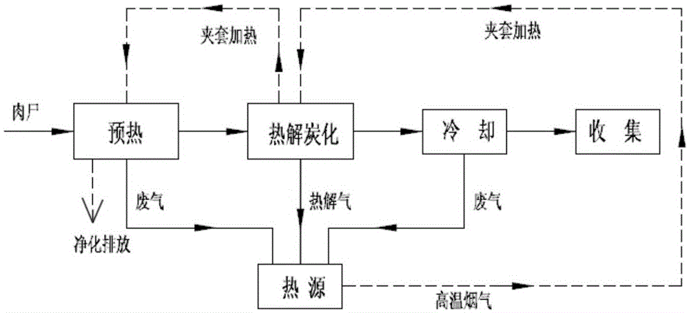
[0060] figure 1 It is the process flow diagram of the continuous pyrolysis carbonization method for embodiment one meat corpse; as figure 1 As shown, a method for continuous pyrolysis and carbonization of meat corpses, including preheating, pyrolysis and carbonization, cooling and pyrolysis gas recycling, is characterized in that:

[0061] (a) Preheating part: place the material basket 5 with a length of 1 in which the carcasses are placed in the preheating chamber 1 with oxygen insulation, normal pressure and 100-300°C, and carry out jacketed pretreatment to ensure that the temperature in the preheating chamber 1 In an oxygen barrier state;

[0062] (b) Pyrolysis and carbonization part: After pretreatment, the material basket 5 is continuously pushed into the carbonization chamber 2 with a working length of L to keep the carbonization chamber 2 in a sealed and oxygen-isolated state, and the heat source heats the carbonization chamber 2 in a jacketed manner, so that The meat...

Embodiment 2

[0073] figure 2 It is a schematic diagram of the overall structure of the continuous pyrolysis and carbonization device for meat corpses in Embodiment 2; figure 2 As shown, a continuous pyrolysis and carbonization device for meat corpses includes a preheating chamber 1, a carbonization chamber 2, a cooling chamber 3, a pyrolysis gas recycling unit 4, and a material basket 5. The material basket 5 is used to place meat corpses. The preheating chamber 1 and the cooling chamber 3 are placed at both ends of the carbonization chamber 2 and communicate with the carbonization chamber 2 respectively;

[0074] The preheating chamber 1 includes a first furnace body 10, a first furnace 11 and a first guide rail 12, and the first feeding end 13 of the preheating chamber 1 is provided with a first furnace door 14 that can be lifted and lowered to play a sealing role; Form the first air duct 15 between the first furnace 11 outer wall and the inner wall of the first furnace body 10; Push...

Embodiment 3

[0101] Figure 4 It is a top view of the third continuous pyrolysis carbonization device for meat carcass in the embodiment of the present invention; Figure 7 It is a partial cross-sectional view of the combustion chamber A-A of Embodiment 3 of the present invention. Such as Figure 4 As shown, in this embodiment, the preheating chamber 1 and the cooling chamber 3 can accommodate two material baskets, and both can accommodate the same number of material baskets. Such as Figure 7 As shown, in this embodiment, the combustion chamber 42 is provided with three gas barriers 430, the gas barriers 430 divide the combustion chamber 42 into four spaces, and the height of the gas barriers 430 is lower than that of the combustion chamber 42 The gas circulates through the gap 440 between the gas blocking wall 430 and the inner wall of the combustion chamber 42 . Other structures and connection relationships of this embodiment are basically the same as those of Embodiment 2, and need...


PUM


Abstract

The present invention relates to a meat carcass continuous pyrolysis carbonization method, a preheating chamber (1), a carbonization chamber (2) and a cooling chamber (3) liftable furnace door are used for controlling a material basket (5) in a carbonization chamber (2) to move to a cooling chamber under the transport effect of a guide rail, meanwhile another material basket (5) is pushed by a front material pushing machine and the guide rail to the carbonization chamber (2) for pyrolysis carbonization, each material basket is pushed, all material baskets in the carbonization chamber (2) move forward together by the length of one material basket, and the material basket pushed from the carbonization chamber (2) enters into the cooling chamber (3) for cooling. The meat carcass continuous pyrolysis carbonization method achieves continuity and orderliness of the pyrolysis process, and is high in efficiency, and labor cost saving.

Description

Technical field: [0001] The invention relates to the technical field of organic waste treatment, in particular to a continuous pyrolysis and carbonization method for carcasses. Background technique: [0002] In recent years, with the development of agricultural technology and the increase of regional breeding density, as well as the spread of viruses such as bird flu, the number of animal deaths has increased year by year, and a series of environmental pollution and health hazards caused by dead livestock and poultry have attracted much attention. If the dead livestock and poultry are not treated in a timely and harmless manner, it is easy to cause the occurrence and spread of major animal diseases, and improper treatment will cause environmental pollution. Recently, the harmless treatment of sick and dead livestock and poultry has gradually been adopted by the industry as a more effective resource-based treatment technology. [0003] Chinese Invention Patent Publication CN...

Claims


Application Information

Patent Timeline
IPC IPC(8): C10B53/00C10B57/08
Inventor 沈润良
Owner CHANGXING CAZENOVE FUNANCE IND CO LTD
Learn More