
Washing machine

A washing machine and machine body technology, applied in the field of washing machines, can solve the problems of large space occupation, inconvenient maintenance, troublesome cleaning of filter components, etc., and achieve the effects of reducing air pressure loss, convenient installation/disassembly, and convenient separation of water and electricity

Active Publication Date: 2015-11-04
HAIER GROUP TECHN R&D CENT
View PDF8 Cites 7 Cited by
  • Summary
  • Abstract
  • Description
  • Claims
  • Application Information

AI Technical Summary

Problems solved by technology

However, because the rinsing water has many impurities and the water quality is unstable, the solution 1 cannot really solve the water quality problem of the rinsing water
Moreover, this solution usually requires manual cleaning of the water storage tank and filter screen, which is inconvenient for maintenance
[0009] Option 2 uses a reverse osmosis filter to purify laundry wastewater, which not only requires the use of a high-pressure pump, but also has a slow purification rate, and the water output is difficult to meet the normal use requirements of the washing machine
In addition, this solution requires regular replacement of the reverse osmosis filter, which is costly
[0010] Option 3 uses large-scale water treatment devices and auxiliary equipment such as ozone generators to purify laundry wastewater. These auxiliary equipment are not only expensive in themselves, occupy a large space, but also require many supporting devices and related cleaning devices, further greatly increasing equipment costs and maintenance. cost, totally unsuitable for ordinary household use
[0011] In addition, in prior art washing machines that have a circulating water filtration system, such as the washing machines according to the aforementioned schemes 1 and 2, they do not have the automatic cleaning function of the filter assembly, resulting in troublesome cleaning of the filter assembly or frequent replacement of the filter assembly.

Method used


Image

  • Washing machine
  • Washing machine
  • Washing machine

Examples


Embodiment Construction

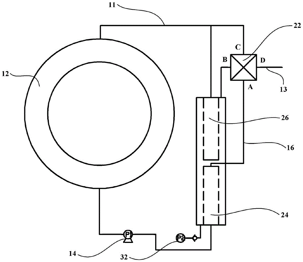
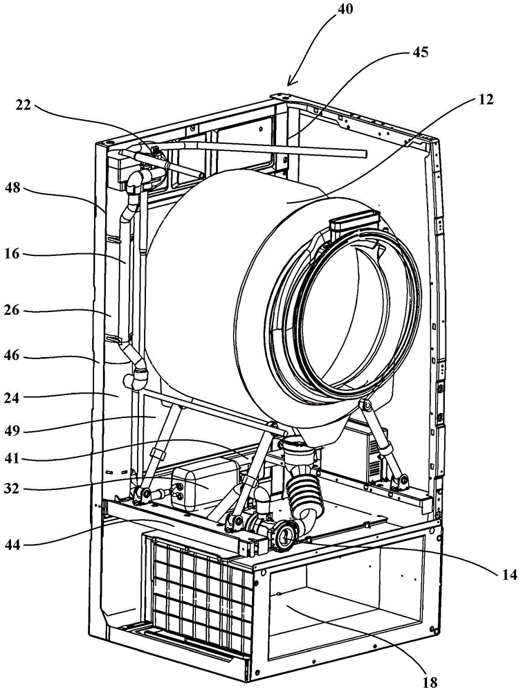
[0041] figure 1 is a schematic schematic diagram of a washing machine according to an embodiment of the present invention. The washing machine may include a washing tub 12, a drain pump 14, and a filter assembly. The washing tub 12 is generally composed of an outer tub and an inner tub that can rotate in the outer tub. The bottom of the washing tub 12 is provided with a drain port, and the drain port communicates with the filter assembly via a drain pump 14 through a pipeline. According to needs, for example, in the washing program or rinsing program of the washing machine, the water in the washing tub 12 can be pumped out, transported to the filter assembly for filtering, and then circulated back to the washing tub 12 for reuse.

[0042] The filter assembly of the embodiment of the present invention uses sieving as the separation principle, which can effectively reduce the residual lint of clothes, and can effectively remove particles, colloids, bacteria, microorganisms and...


PUM


Abstract

The invention provides a washing machine comprising a filtering assembly configured to filter water pumped out of a washing drum of the washing machine to recycle the water into the washing drum for reuse, and an air pump configured to air wash the filtering assembly via air flows. An air inlet is formed in the bottom of the filtering assembly to receive air flows, so the filtering assembly can be air washed; and the air pump is arranged on the peripheral wall of a washing machine housing adjacent to the filtering assembly. Distribution positions and / or installation methods of the filtering assembly and the air pump are specially designed, so inside space of the washing machine can be fully utilized; the filtering assembly can be firmly and reliably installed and pressure of air flows pumped by the air pump is even, so the distance between an air inlet of the air pump and the air inlet of the filtering assembly can be shortened and air flow pressure loss can be reduced; and the filtering assembly can be well cleaned to restore primary performance state.

Description

technical field [0001] The invention relates to a washing machine, in particular to a washing machine with a circulating water filtering system. Background technique [0002] The working process of conventional washing machines usually includes water intake, washing-spin-drying-drainage, multiple rinsing-spin-drying-drainage, etc., wherein each rinse needs to consume a large amount of clean water. Generally speaking, the water consumption of the entire working process of the existing pulsator washing machine can reach 20-30 liters per kilogram of clothing, while the water consumption of the entire working process of the existing drum washing machine can also reach 12 liters of water per kilogram of clothing. That is to say, when the existing conventional washing machine (no matter the pulsator type washing machine or the drum type washing machine, and no matter whether it is a semi-automatic washing machine or a fully automatic washing machine) works, the laundry waste water...

Claims


Application Information

Patent Timeline
Patent Type & Authority Applications(China)
IPC IPC(8): D06F35/00D06F39/10
Inventor 肖田劳春峰郝世龙张静静王春旭
Owner HAIER GROUP TECHN R&D CENT
Learn More