High-efficiency direct drive type pumping unit with single movable pulley and single fixed pulley

A direct drive pumping unit technology, which is applied in the fields of mining fluid, wellbore/well components, earthwork drilling and production, etc. It can solve the problems of transmission system impact, hidden danger of equipment safety, and impact on life, and achieve the need to reduce the torque of the motor , workover and maintenance are convenient, and the effect of prolonging the service life

Active Publication Date: 2015-11-04
ZHEJIANG DEQING XICHUAN ELECTRICAL SCI & TECH
View PDF8 Cites 3 Cited by
  • Summary
  • Abstract
  • Description
  • Claims
  • Application Information

AI Technical Summary

Problems solved by technology

The existing new pumping units can be roughly divided into several types according to their structural characteristics, such as complete machine displacement, guide arm backward rotation displacement, electric displacement, etc. Among them, the complete machine displacement needs to move the entire equipment backward. Operation, so the structure is complicated and the consumables are large, and the safety is poor, which is far less flexible than other methods of giving way
The backward rotation of the guide arm generally has a large and complex structure, and does not use its own driving parts as the driving source for the guide arm rotation, so the operation is cumbersome. On the one hand, the backward rotation of the guide arm limits the space for front and rear adjustment of the guide arm when the wellhead is aligned. On the other hand, the guide arm is flipped backwards and vacated. If there is a failure of the lifting belt and manual operation is required, the safety is not hig

Method used


Image

  • High-efficiency direct drive type pumping unit with single movable pulley and single fixed pulley
  • High-efficiency direct drive type pumping unit with single movable pulley and single fixed pulley
  • High-efficiency direct drive type pumping unit with single movable pulley and single fixed pulley

Examples


Example Embodiment

[0021] The specific embodiments of the present invention will be described in detail below with reference to the accompanying drawings.

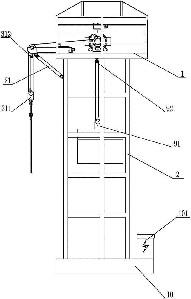
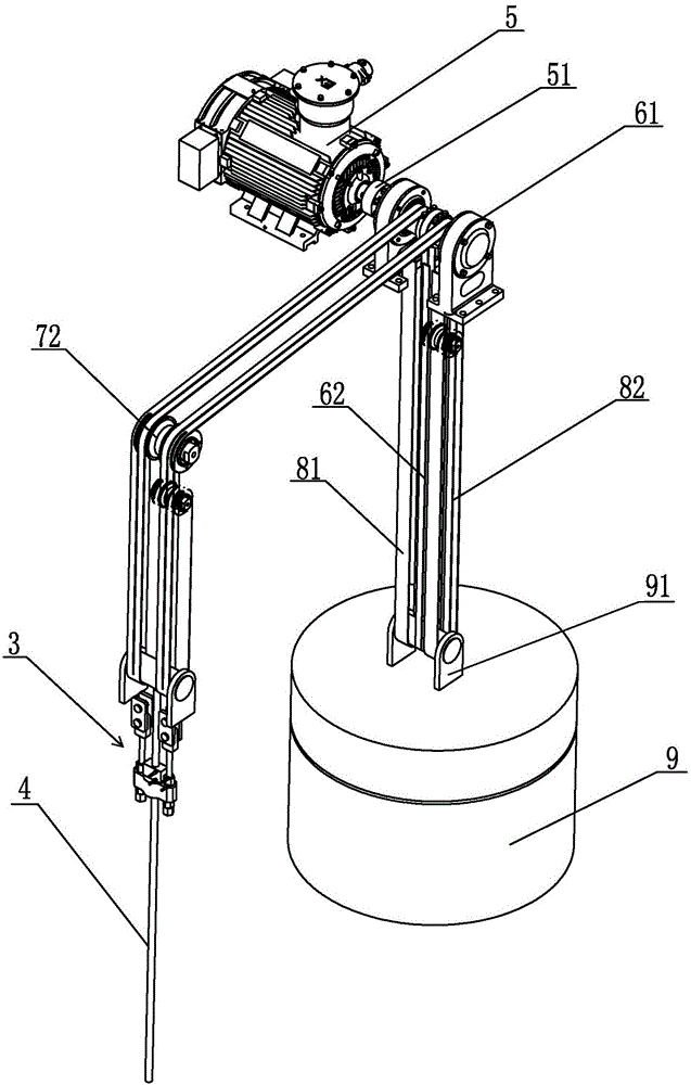
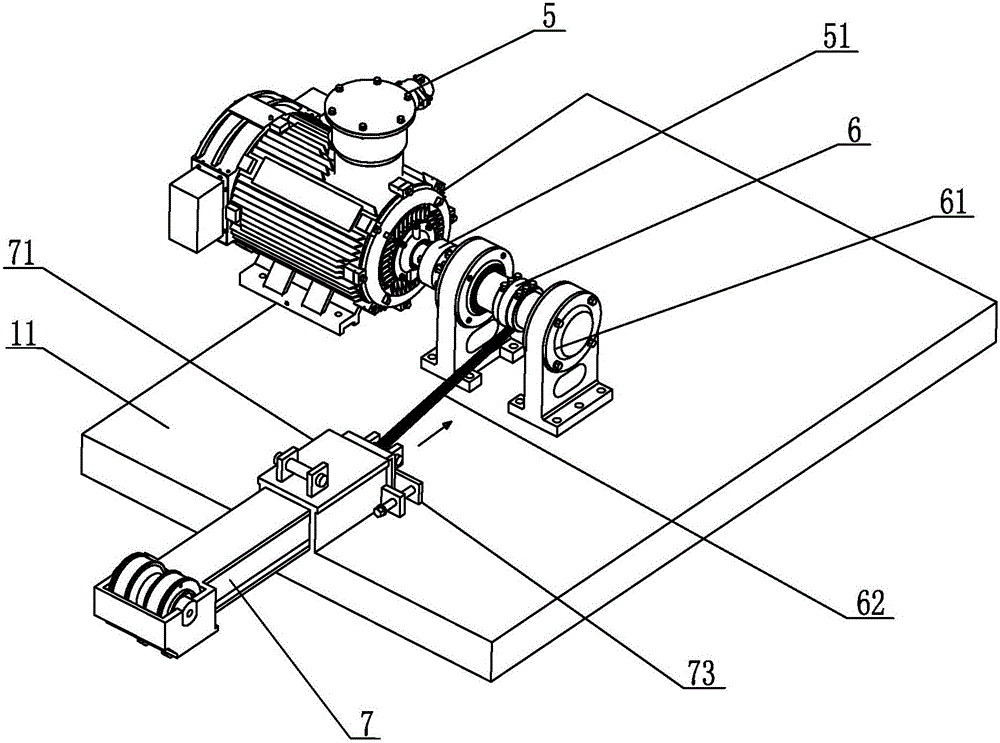
[0022] like Figure 1-Figure 9 The shown high-efficiency direct-drive pumping unit with single-acting pulley and single-fixed pulley includes a tower 2 fixed on a cement foundation 10, and a platform welding frame 1 is fixed on the top of the tower 2, and the platform is The upper platform 11 of the welding frame 1 is provided with a motor 5, a driving wheel 6, a guide seat 71 and a guide arm 7. The driving wheel 6 is fixed in the middle of the upper platform 11 through the driving wheel bracket 61, and the middle of the driving wheel 6 is rolled A first steel belt 62 is wound around, the motor 5 is fixed on one side of the driving wheel 6 and is connected with the driving wheel 6 through the coupling 51 , the guide seat 71 is fixed on one end of the upper platform 11 , and the guide seat 71 The upper end face of the guide arm 7 is provided...


PUM


Abstract

The invention relates to a high-efficiency direct drive type pumping unit with a single movable pulley and a single fixed pulley. The high-efficiency direct drive type pumping unit comprises a tower which is fixed on a cement foundation. A platform welding rack is fixed at the top of the tower. The upper platform of the platform welding rack is provided with a motor, a driving wheel, a guiding seat and a guiding arm. According to the high-efficiency direct drive type pumping unit, a direct motor driving manner is used. Furthermore a sucker rod and a counterweight end are respectively provided with a fixed pulley assembly and a movable pulley assembly. A requirement for a motor torque is greatly reduced, thereby reducing cost, facilitating maintenance and improving the integral operation efficiency of the pumping unit. Furthermore the high-efficiency direct drive type pumping unit is provided with a winch first steel band, and therefore automatic elevation of a counterweight can be realized and dodging and resetting of a front guiding arm can be easily performed, thereby realizing more convenient well maintenance. Furthermore a drawer type structure is adopted for dodging and resetting of the guiding arm, thereby realizing higher safety.

Description

technical field [0001] The invention relates to the field of petroleum machinery, in particular to a high-efficiency direct-drive oil pumping unit with a single-acting pulley and a single-fixed pulley. Background technique [0002] The existing external rotor motor direct drive type pumping unit has the simplest transmission system, only the permanent magnet motor is used to directly drive the hoisting wheel to drive the sucker rod and the counterweight to reciprocate up and down. Significant, but also has its drawbacks or shortcomings: [0003] In the process of oil pumping operations in oilfields, it is often necessary to perform well workover or well cleaning operations. At this time, structures such as the donkey head or guide wheel or guide arm of the oil pumping equipment need to make room for the vertical above the oil well, so as to facilitate the operation. Equipment hoisting sucker rod. The existing new pumping units can be roughly divided into several types acco...

Claims


Application Information

Patent Timeline
IPC IPC(8): E21B43/00
Inventor 李骏董元柏
Owner ZHEJIANG DEQING XICHUAN ELECTRICAL SCI & TECH
Why Eureka
Try Eureka