Numerical control machine tool thermal error compensating method

A technology of numerical control machine tool and compensation method, which is applied in the direction of program control, computer control, general control system, etc., and can solve problems such as poor implementability, difficult temperature compensation points, and cumbersome methods

Active Publication Date: 2015-11-04
上海电气自动化集团有限公司
View PDF5 Cites 37 Cited by
  • Summary
  • Abstract
  • Description
  • Claims
  • Application Information

AI Technical Summary

Problems solved by technology

The traditional method is cumbersome and has poor implementability, and it is difficult to obtain a suitable temperature compensation point

Method used


Image

  • Numerical control machine tool thermal error compensating method
  • Numerical control machine tool thermal error compensating method
  • Numerical control machine tool thermal error compensating method

Examples


Embodiment Construction

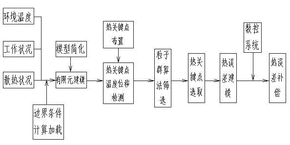
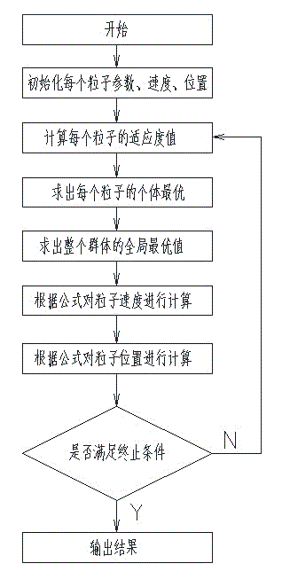
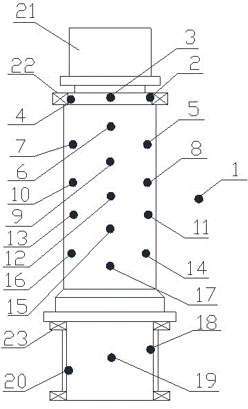
[0028] Such as figure 1 , figure 2 and image 3 As shown, the thermal error compensation method of the numerical control machine tool of the present invention comprises the following steps:

[0029] Step 1. Establish the geometric model of the finite element simulation analysis of the spindle structure of the CNC machine tool. During the establishment of the geometric model, the screw holes, oil pipes, oil injection holes, fine chamfers and rounded corners that have little influence on the spindle structure are ignored, and a simple ring is used instead of the spindle. Features of structural bearings and bearing sleeves;

[0030] Step 2. Carry out mesh division and sweep division for the established geometric model. The complex entities of the main shaft and headstock of the main shaft structure are divided into meshes, and the simple entities of the bearing and bearing sleeve of the main shaft structure are divided by sweep. Bonding is selected for the contact relationshi...


PUM


Abstract

The invention discloses a numerical control machine tool thermal error compensating method. The method comprises the following steps of making a finite element simulation analysis geometric model of a numerical control machine tool main shaft structure and simplifying the geometric model; loading a proper boundary condition according to the working state and the working environment of the main shaft structure; performing thermodynamics and statics finite element simulation analysis on the simplified geometric model; selecting temperature and thermal deformation values of a certain number of points from the analysis result; screening the data through a particle swarm optimization algorithm; selecting optimum four-point temperature values as the numerical control machine tool thermal error compensating parameters and making an error compensating model to achieve numerical control machine tool thermal error compensation. On the basis of finite element simulation analysis, the method adopting the particle swarm optimization algorithm to acquire key temperature points for thermal error compensation and using the temperature measuring values of the key temperature points as the numerical control machine tool thermal error compensating basis makes the selection of thermal error temperature measuring points simplified. The machine tool thermal errors are effectively alleviated. The machine tool processing precision is further improved.

Description

technical field [0001] The invention relates to a thermal error compensation method of a numerical control machine tool. Background technique [0002] With the rapid development of modern machinery manufacturing technology, high flexibility, high efficiency, high quality, high precision, high integration and high intelligence processing technology has become the most important component and development direction of modern machinery manufacturing, and has become a national industry The important means of development level has been widely valued by countries all over the world, and then higher and higher requirements are put forward for the manufacturing and processing accuracy of CNC machine tools. However, with the further improvement of the precision of CNC machine tools, thermal errors have gradually become the main factor affecting the machining accuracy of CNC machine tools. Research shows that among the many error sources that cause machine tool deformation, the geomet...

Claims


Application Information

Patent Timeline
Patent Type & Authority Applications(China)
IPC IPC(8): G05B19/404
CPCG05B19/404
Inventor 陶益民蒋知峰施群张雪明印叶婷吴曼菁
Owner 上海电气自动化集团有限公司
Why Eureka
Try Eureka