Planar array antenna pattern synthesis method based on sub arrays

A planar array antenna and pattern synthesis technology, applied to antennas, electrical components, etc., can solve the problems of poor versatility and achieve the effects of good versatility, improved calculation efficiency, and improved calculation accuracy

Active Publication Date: 2015-11-04
THE 724TH RES INST OF CHINA SHIPBUILDING IND
View PDF5 Cites 10 Cited by
  • Summary
  • Abstract
  • Description
  • Claims
  • Application Information

AI Technical Summary

Problems solved by technology

This method is simple and easy to implement, but it will no longer be applicable to complex beam synthesis problems of array antennas, and its versatility is not good

Method used


Image

  • Planar array antenna pattern synthesis method based on sub arrays
  • Planar array antenna pattern synthesis method based on sub arrays
  • Planar array antenna pattern synthesis method based on sub arrays

Examples


Embodiment Construction

[0023] In order to make the object, technical solution and advantages of the present invention clearer, the present invention will be further described in detail below in conjunction with the accompanying drawings and embodiments. Taking a 50×64 array whose subarrays are 1×4 module planar array antenna sector wide beam synthesis problems as an example, the specific implementation steps of the planar array antenna pattern synthesis method based on subarrays are illustrated:

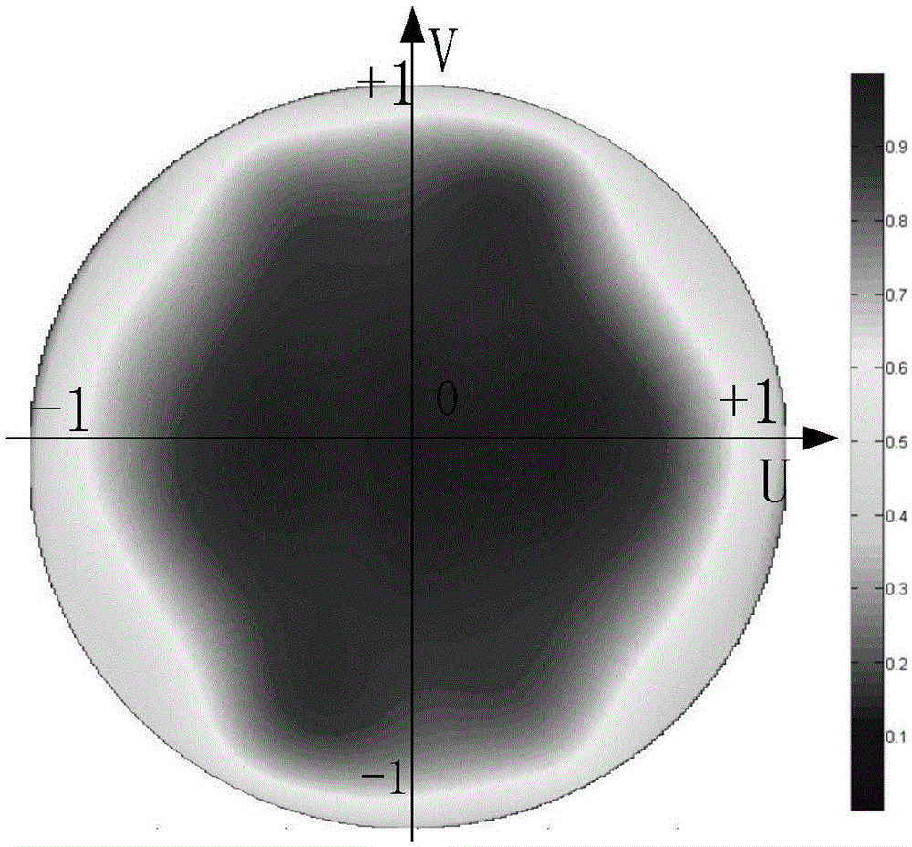
[0024] Step 1: Obtain the array unit pattern data P in the integrated array 0 ,like figure 1 As shown, the array size of the integrated array is obtained: 50 rows, 64 columns, row spacing d y =0.52λ 0 , column spacing d x =0.54λ 0 ,λ 0 is the working wavelength of the antenna. The size of the sub-array is 1 row and 4 columns. The target pattern is a fan-shaped wide beam. The 3dB width of the azimuth plane is 1.6°, and the 3dB width of the elevation plane is 10°. In this example, take the array patte...


PUM


Abstract

The invention discloses a planar array antenna pattern synthesis method based on sub arrays. A hybrid optimization algorithm combining an improved iterative Fourier transform method (IFT) and multiple intelligent optimization algorithms is adopted to perform pattern synthesis design on a sub array planar array antenna, a sub array optimization variable construction method is adopted in the design process, and the synthesis design is concise. The synthesis method further takes an influence of a mutual coupling factor between antenna units into account, and an optimization result is accurate. The method aims at a synthesis design problem of the sub array form planar array antenna, and has the advantages of high calculation efficiency and good universality.

Description

technical field [0001] The invention belongs to the technical field of radar antennas, and relates to a method for synthesizing the pattern of a plane array antenna based on a subarray. Background technique [0002] A phased array radar system generally contains thousands to tens of thousands of radiation elements. If the beamforming technology is applied at the element level, the system overhead will be greatly increased, and the complexity of the array adaptive algorithm and related calculations will be greatly increased, making it difficult to meet Real-time requirements, as well as an equal number of high-frequency channels, A / D conversion and weighting processing, etc., the system is very complex and the hardware cost is high. By dividing a large array into sub-arrays, analog beamforming is used between sub-array internal units, and digital beamforming is used between sub-array levels, which can not only reduce the number of channels required for transmission and recept...

Claims


Application Information

Patent Timeline
Patent Type & Authority Applications(China)
IPC IPC(8): H01Q3/30
Inventor 丛友记
Owner THE 724TH RES INST OF CHINA SHIPBUILDING IND
Why Eureka
Try Eureka