A magnetic fluid power generation system that directly converts thermal energy into electrical energy

A magnetic fluid power generation and thermal energy conversion technology, applied in electrical components, electromechanical devices, joint combustion mitigation, etc., can solve problems such as inability to achieve pollution-free power generation, increase system manufacturing costs, and inconsistent development goals, and achieve material and safety performance. The effect of low requirements, no preparation work, and easy operation

Active Publication Date: 2018-02-27
XI AN JIAOTONG UNIV
View PDF4 Cites 0 Cited by
  • Summary
  • Abstract
  • Description
  • Claims
  • Application Information

AI Technical Summary

Problems solved by technology

[0004] Although coal-fired magnetic fluid power generation is relatively advanced and energy-saving among existing power generation technologies, this design and power generation method still has the following disadvantages: First, it still needs to burn fossil fuels to provide heat energy, which has a certain amount of carbon emissions, and low energy consumption. The development goals of carbon environmental protection are inconsistent; the second is to add easily ionized substances, such as alkali metal compounds such as potassium and cesium, to the magnetic fluid in order to improve the conductivity. Their properties are very active, which is not only dangerous to operate but also requires a certain preparation process; Active alkali metal compounds are added to the fluid, which has high requirements on the material and equipment safety of the magnetic fluid flow channel, and increases the manufacturing cost of the entire system
[0005] Compared with thermal power generation, coal-fired magnetic fluid power generation technology reduces the use of fossil fuels to a certain extent, but it still relies on coal and cannot achieve truly pollution-free power generation
In addition, due to the addition of alkali metal compounds, there are high requirements for the safety of equipment and operating processes, which makes it a lot of practical problems to put it into use in a large area

Method used


Image

  • A magnetic fluid power generation system that directly converts thermal energy into electrical energy
  • A magnetic fluid power generation system that directly converts thermal energy into electrical energy
  • A magnetic fluid power generation system that directly converts thermal energy into electrical energy

Examples


Embodiment Construction

[0024] The present invention will be further described in detail below in conjunction with the accompanying drawings.

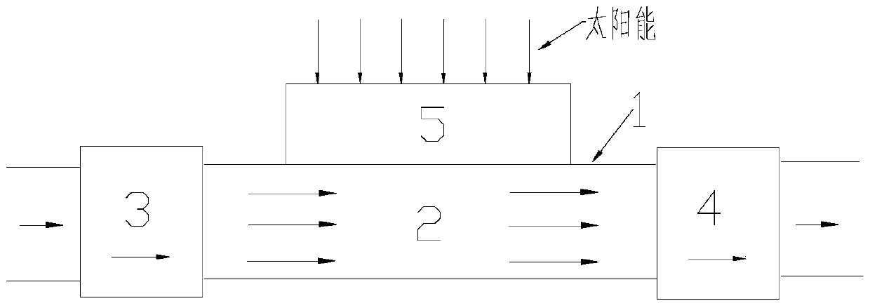
[0025] see figure 2 and Figure 4 , the present invention is a magnetic fluid power generation system that directly converts thermal energy into electrical energy, including an annular closed channel 1, and the channel 1 is provided with a first one-way valve 3 and a second one-way valve 4 arranged in the same direction, the channel 1 is filled with magnetic fluid 2, the one-way valve is used to control the flow direction of the magnetic fluid 2, and a solar panel 5 for heating the magnetic fluid 2 by means of solar energy is arranged between the two one-way valves;

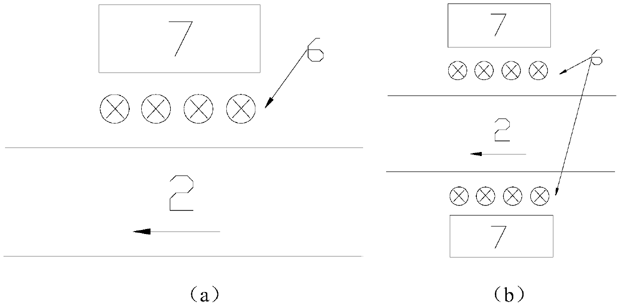
[0026] It also includes a magnet 7 arranged parallel to the channel 1. A group of wires 6 perpendicular to the magnetic field are arranged in the gap between the magnet 7 and the channel 1. Both ends of the wire 6 are connected to a power storage device or connected to a power grid. When work...


PUM


Abstract

The invention discloses a magnetic fluid power generation system which directly converts thermal energy into electric energy, which comprises a ring-shaped closed channel, the channel is provided with a first check valve and a second check valve arranged in the same direction, and the channel is filled with For magnetic fluid, a solar panel for heating the magnetic fluid with the help of solar energy is arranged between the two one-way valves; it also includes a magnet arranged in parallel with the passage, and a group of wires perpendicular to the magnetic field are arranged in the gap between the magnet and the passage, and the two wires of the wire The terminal is connected to the power storage device or connected to the grid. When working, use solar panels to absorb solar heat, heat the magnetic fluid in the channel to make it expand, the heated magnetic fluid starts to flow due to expansion, and flows in one direction in the annular channel at a certain speed after passing through the one-way valve. When the fluid flows through the channel near the magnet at a certain speed, a flowing magnetic field is formed between the magnetic fluid and the magnet, and the relative motion of the two makes the wire cut the magnetic induction line and generate current in the wire.

Description

Technical field: [0001] The invention belongs to the field of energy conversion, and relates to the power generation of magnetic fluid, in particular to a magnetic fluid power generation system directly converting heat energy into electric energy. Background technique: [0002] Magnetic fluid is a new type of functional material, which not only has the fluidity of fluid but also has the magnetism of solid magnetic materials, and has a wide range of application prospects. Magnetic fluid power generation generally refers to coal-fired magnetic fluid power generation technology, which uses conductive gas as a conductive fluid, directly heats it with fossil fuels to ionize it into a conductive ion flow, and then makes it flow in a magnetic field and cuts magnetic induction lines to generate current. It can not only improve the utilization rate of coal resources, but also has the characteristics of low pollution. The schematic diagram of a coal-fired magnetic fluid power genera...

Claims


Application Information

Patent Timeline
Patent Type & Authority Patents(China)
IPC IPC(8): H02K44/08
CPCY02E20/14
Inventor 谢永慧袁瑞山王宇璐张荻
Owner XI AN JIAOTONG UNIV
Why Eureka
Try Eureka