
Breathing machine voltage regulating system and control method

A pressure regulation system and control method technology, applied in the field of medical equipment, can solve the problems of PID algorithm that is easy to generate pressure, high error rate, and affects output stability, etc.

Active Publication Date: 2015-11-11
HUNAN MICOME ZHONGJIN MEDICAL SCI & TECH DEV CO LTD
View PDF9 Cites 2 Cited by
  • Summary
  • Abstract
  • Description
  • Claims
  • Application Information

AI Technical Summary

Problems solved by technology

The software PID control technology is a kind of closed-loop control, usually with the speed of the turbo fan, the output air pressure or flow as the negative feedback, however, due to the characteristics of the motor's rotational inertia and the elasticity of the air, there is a long delay in the output of the feedback signal, It is easy to cause the accumulation of PID integral items, which will cause the motor speed to oscillate and affect the stability of the output. If the sampling frequency of PID is reduced, it will affect the response time of the motor system and affect the comfort of the patient.
Disadvantages of using PID control technology: 1. The delay of the output feedback of the turbo blower causes the PID algorithm to easily generate pressure and flow rate fluctuations, thereby reducing the comfort of the ventilator; 2. The application software PID algorithm takes up relatively high system resources Used for data acquisition and calculation, and affected by A / D conversion, the error rate is high, the stability is poor, and the response speed is slow
Therefore, the patent still uses the PID algorithm to realize the adjustment of the ventilator pressure, and still does not get rid of the above-mentioned defects of the PID algorithm

Method used


Image

  • Breathing machine voltage regulating system and control method
  • Breathing machine voltage regulating system and control method
  • Breathing machine voltage regulating system and control method

Examples


Embodiment

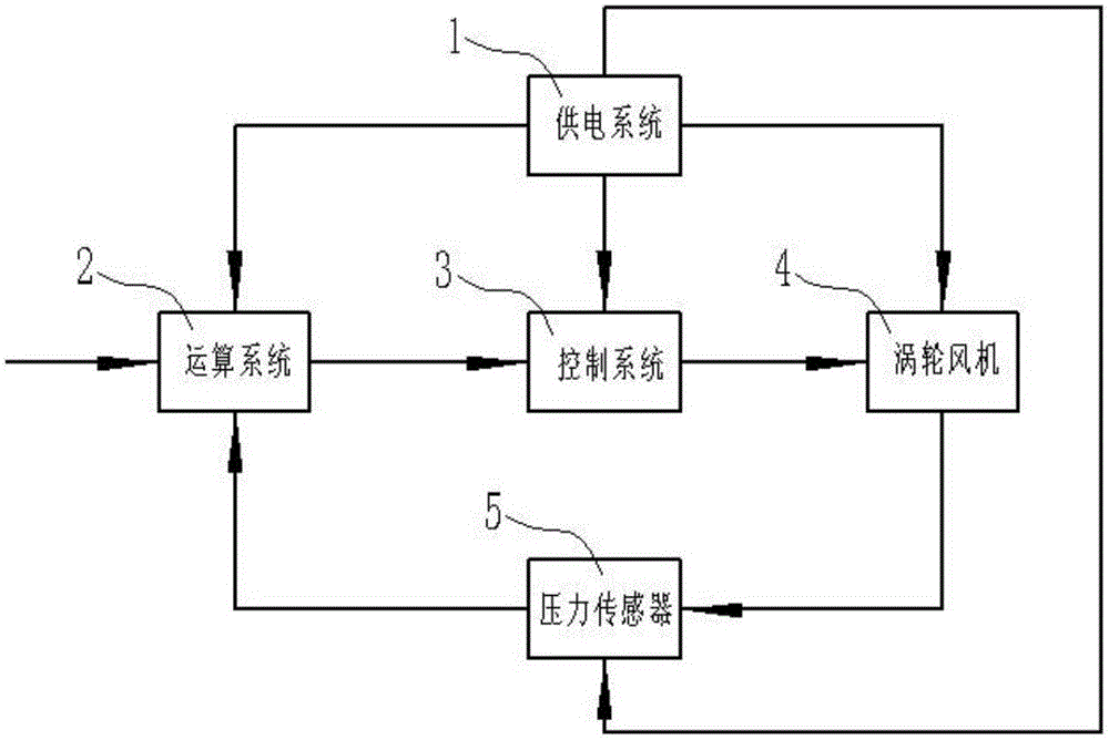
[0047] like figure 1 , 2 As shown, a ventilator pressure regulation system provided by the present invention includes a power supply system 1, a computing system 2, a control system 3, a pressure sensor 5 and a turbo fan 4; The system 3, the pressure sensor 5 and the turbo fan 4 are electrically connected; the computing system 2, the control system 3 and the turbo fan 4 are connected in sequence; the pressure sensor 5 is arranged at the air outlet of the turbo fan 4, and the The pressure sensor 5 is connected with the computing system 2;

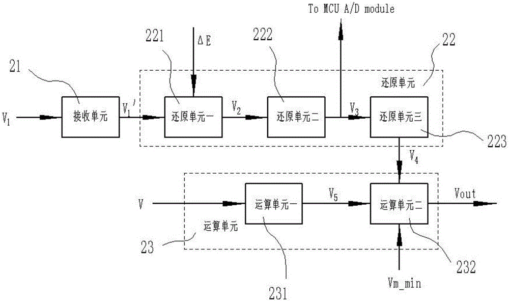
[0048] The input terminal of the computing system 2 receives an input voltage V, and the input voltage V corresponds to an input pressure P; the pressure sensor 5 collects the output pressure P of the turbo blower 4 0 After, the output voltage V 1 and fed back to the computing system 2; the computing system 2 receives the output voltage V of the pressure sensor 5 1 , output the motor control voltage Vout after calculation and processing ...


PUM


Abstract

The invention discloses a breathing machine voltage regulating system and a control method. The method comprises the following steps that an arithmetic system receives input voltage, a pressure sensor collects output pressure of a turbofan and feeds data back to the arithmetic system, the arithmetic system performs arithmetic treatment and then outputs motor control voltage to a control system, and the control system controls the rotation speed of the turbofan according to the motor control voltage to control the output pressure of the turbofan. According to the breathing machine voltage regulating system and the control method, the air pressure output by the turbofan is adopted as closed-loop control of feedback, similar integral windup controlled by PID cannot be generated, a motor is rapid in response, the response time of a breathing machine is significantly shortened, and the comfortableness of the breathing machine is significantly improved.

Description

technical field [0001] The invention belongs to the field of medical devices, in particular to a pressure regulating system and a control method for a ventilator. Background technique [0002] In modern clinical medicine, ventilator, as an effective means to artificially replace the function of spontaneous ventilation, has been widely used in respiratory failure caused by various reasons, anesthesia and respiratory management during major surgery, respiratory support treatment and emergency resuscitation. It occupies a very important position in the field of modern medicine. A ventilator is a vital medical device that can prevent and treat respiratory failure, reduce complications, and save and prolong patients' lives. [0003] A ventilator is a medical device for the purpose of outputting air at a certain pressure or flow rate to assist patients with respiratory insufficiency or unable to breathe spontaneously due to special circumstances. The turbo blower powered by the ...

Claims


Application Information

Patent Timeline
Patent Type & Authority Applications(China)
IPC IPC(8): A61M16/00
Inventor 戴征刘炜徐勤鹏
Owner HUNAN MICOME ZHONGJIN MEDICAL SCI & TECH DEV CO LTD
Learn More