Continuous loose fiber dyeing device

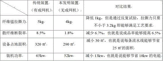
A dyeing device and loose fiber technology, which is applied in spray/jet textile material treatment, textile material carrier treatment, etc., can solve the problems of complex assembly line equipment, large footprint, and large power consumption, so as to improve spinnability and occupy a large area. Effect of reduced land area and reduced production cost

Inactive Publication Date: 2015-11-11
SHAOXING GUOZHOU TEXTILE NEW MATERIAL
6 Cites 5 Cited by

AI-Extracted Technical Summary

Problems solved by technology

Furthermore, due to the existence of the web forming machine, the entire assembly line equipment is complicated, occupies a large area, and requir...

Abstract

The invention discloses a continuous loose fiber dyeing device. The continuous loose fiber dyeing device consists of a bale plucker, a cotton box, a sprinkling-rolling type dyeing machine and a lap former which are arranged in sequence. The continuous loose fiber dyeing device has the advantages of being high in rate of finished products, small in occupied area, low in production cost and the like.

Application Domain

Technology Topic

Image

  • Continuous loose fiber dyeing device
  • Continuous loose fiber dyeing device
  • Continuous loose fiber dyeing device

Examples

  • Experimental program(1)

Example Embodiment

[0014] Hereinafter, the present invention will be further described in detail through the accompanying drawings and embodiments.
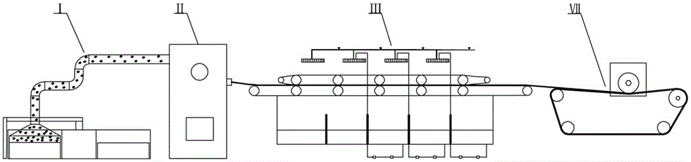
[0015] Such as figure 1 Shown: a continuous loose fiber dyeing device, consisting of a cotton grabbing machine I, a cotton box II, a pad dyeing machine III and a coiling machine VII.
[0016] The following is the process flow of processing loose fibers by the continuous loose fiber dyeing device of the present invention:
[0017] (1) Cotton grabbing: grab the fiber from the pile of loose fibers through the grabbing machine I, and feed the fluffy loose fibers into the cotton box II.
[0018] (2) Carpet formation: The fluffy loose fibers are pressed into cotton blanket-like loose fibers through the cotton box Ⅱ, and the blanket fibers are transported to the shower type dyeing machine Ⅲ.
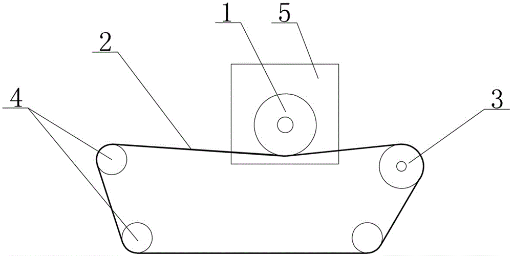
[0019] (3) Pad dyeing: through the pad dyeing machine Ⅲ, it is conveyed by the horizontal guide belt and is squeezed and sprayed alternately for multiple sets of pad dyeing, and the loose fiber after the pad dyeing Convey to the coiler Ⅶ.
[0020] (4) Rolling: Rolling through the rolling machine Ⅶ to complete the dyeing process.
[0021] The continuous loose fiber dyeing device of the present invention eliminates the traditional web forming machine. After repeated tests, the tensile and tearing force of the fiber blanket still meets the technological requirements, but the breakage rate of the loose fiber after dyeing is greatly reduced, and the yield rate of the loose fiber It has been significantly improved, and the subsequent spinnability has also been significantly improved; at the same time, after removing the netting machine, the equipment footprint and equipment capital investment are also greatly reduced, and the netting process is also saved. A large amount of electric power is required, and the production cost has been drastically reduced.
[0022] In order to more intuitively reflect the technical effect of the continuous loose fiber dyeing process of the present invention, a comparison table of relevant data compared with the traditional device is attached. The table is as follows:
[0023]
[0024] In addition, in the present invention, the winding machine VII includes a winding roller 1, a transmission mesh belt 2, a driving roller 3, and a plurality of guide rollers 4 that are not on the same line. The transmission mesh belt 2 is wrapped around the driving roller 3 and the guide roller 4 in a closed shape. The roll 1 is pressed on the transmission mesh belt 2. Both ends of the winding roller 1 are supported on the side plate 5.
[0025] The driving roller 3 described above is used to drive the transmission mesh belt 2 in a closed transmission, and the guide roller 4 plays a role of guiding the transmission mesh belt 2.
[0026] When the winding machine is in the standby state, the winding roller 1 and the transmission mesh belt 2 are closely attached. When the winding machine is in operation, the fiber roll and the transmission mesh belt 2 are closely attached, and the transmission mesh belt 2 passes through each other after transmission. The friction force drives the fiber roll to rotate, which can ensure that the linear speed at any point on the outermost layer of the fiber roll is consistent with the transmission speed of the transmission belt 2, and the transmission speed of the transmission belt 2 is constant, so the outermost layer of the fiber roll The linear speed at any point is also constant. Therefore, as long as the transmission speed of the transmission mesh belt 2 is controlled to be consistent with the export speed of the fiber blanket from the front-end equipment, the roll can be stably formed to ensure that the fiber layer and the fiber layer are attached during the roll. It is tightly closed to prevent loose fiber rolls. The overall structure is simple and the roll quality is high.
[0027] The above-mentioned examples are enlightenment, and through the above-mentioned description, relevant staff can make various changes and modifications without departing from the scope of the inventive idea. The technical scope of the present invention is not limited to the content of the description, and the protection scope must be determined according to the scope of the claims.

PUM

no PUM

Description & Claims & Application Information

We can also present the details of the Description, Claims and Application information to help users get a comprehensive understanding of the technical details of the patent, such as background art, summary of invention, brief description of drawings, description of embodiments, and other original content. On the other hand, users can also determine the specific scope of protection of the technology through the list of claims; as well as understand the changes in the life cycle of the technology with the presentation of the patent timeline. Login to view more.

Similar technology patents

Continuous loose stock dyeing technology

InactiveCN105155168AReduce breakage rateImprove yieldLiquid/gas/vapor open-width material treatmentTextile treatment machine partsDyeingSmall footprint
Owner:SHAOXING GUOZHOU TEXTILE NEW MATERIAL

Classification and recommendation of technical efficacy words

  • Improve yield
  • Reduce breakage rate

Krill oil process

Owner:PRONOVA BIOPHARMA NORGE

Method for preparing porous alumina ceramic supporting body with sol as additive

InactiveCN101412620ASolve the cracking problemImprove yieldHoneycombAlumina ceramic
Owner:XI AN JIAOTONG UNIV

Linseed dehulling method

Owner:INNER MONGOLIA JIUDING FOOD
Why Eureka
Try Eureka