Rotary compressor

A rotary compressor and frame technology, applied in the field of compressors, can solve the problems of difficulty in ensuring the uniformity of the clearance between the auxiliary bearing and the crankshaft, inability to guarantee parallelism, and inability to guarantee high efficiency, and achieves simple and reasonable structure, low noise, less wear effect

Active Publication Date: 2015-11-11
GUANGDONG MEIZHI COMPRESSOR +1
View PDF6 Cites 7 Cited by
  • Summary
  • Abstract
  • Description
  • Claims
  • Application Information

AI Technical Summary

Problems solved by technology

However, there are some problems in these solutions, so the compressor with double support structure has not been applied in mass production. The specific problems are as follows:
[0005] First of all, the welding and fixing of the first support cannot guarantee the motor stator and rotor clearance requirements of small clearance and low unbalance required for high efficiency;
[0006] Second, the parallelism between the two supports cannot be guaranteed. Even if the second support is aligned with the auxiliary bearing and the crankshaft, the position of the auxiliary bearing will change due to the influence of the reference after tightening, making it difficult to ensure that the auxiliary bearing is aligned with the crankshaft. Uniformity of crankshaft clearance

Method used


Image

  • Rotary compressor
  • Rotary compressor
  • Rotary compressor

Examples


Embodiment Construction

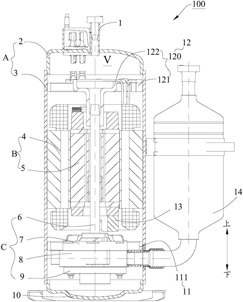
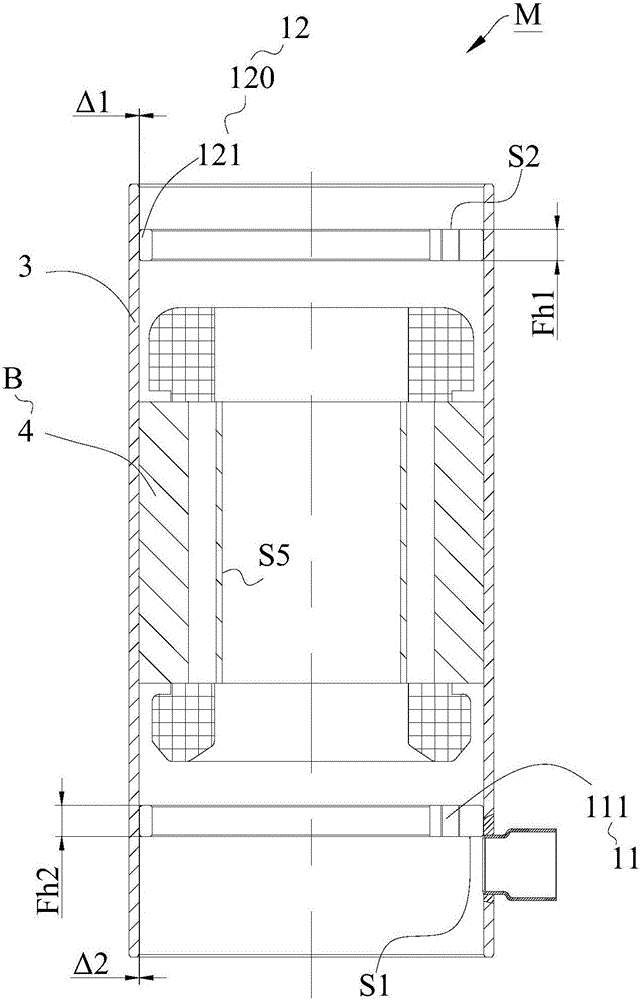
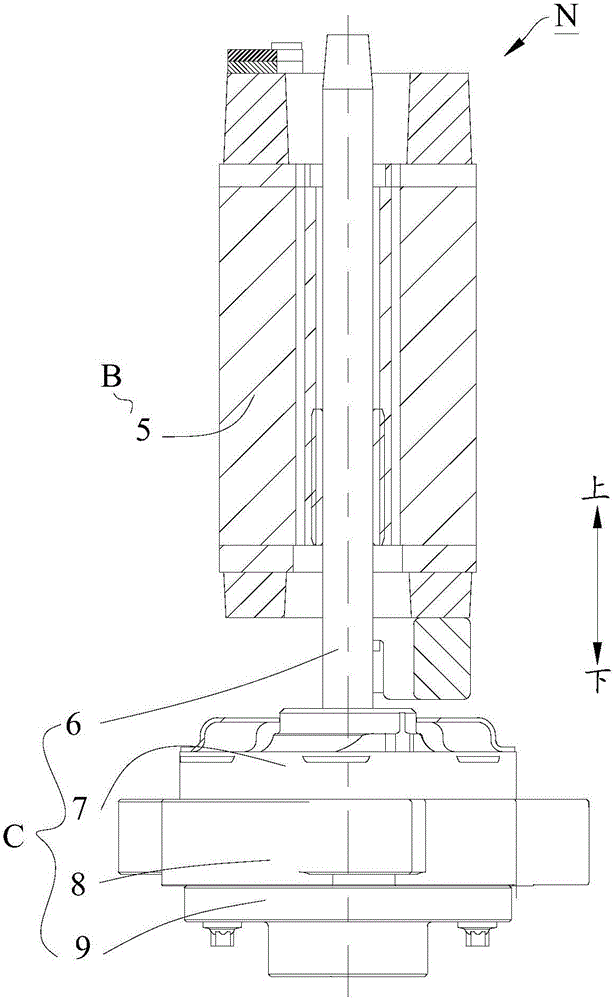
[0033] The embodiments of the present invention will be described in detail below. Examples of the embodiments are shown in the accompanying drawings, wherein the same or similar reference numerals indicate the same or similar elements or elements with the same or similar functions. The embodiments described below with reference to the accompanying drawings are exemplary, and are intended to explain the present invention, but should not be construed as limiting the present invention.

[0034] In the description of the present invention, it should be understood that the terms "center", "longitudinal", "transverse", "length", "width", "thickness", "upper", "lower", "front", " "Back", "Left", "Right", "Vertical", "Horizontal", "Top", "Bottom", "Inner", "Outer", "Clockwise", "Counterclockwise", "Axial" , "Radial", "Circumferential", etc. indicate the orientation or positional relationship based on the orientation or positional relationship shown in the drawings, and are only for the ...


PUM


Abstract

The invention discloses a rotary compressor. The rotary compressor comprises a shell, a compressing component, a motor component, a first machine frame and a supporting component. The peripheral wall of the first machine frame is fixed to the inner wall of the shell. A main bearing, a supplementary bearing or a cylinder or other parts such as a partition board of the compressing component are fixedly connected to the first machine frame. The supporting component comprises a second machine frame and an auxiliary bearing, wherein the peripheral wall of the second machine frame is fixed to the inner wall of the shell, and the auxiliary bearing is fixed to the upper surface of the second machine frame and arranged on the upper portion of a crankshaft in a sleeving mode. According to the rotary compressor, due to the fact that a compressing component and rotor assembly is connected to the shell in a transition mode through the first machine frame and the second machine frame, assembling precision is improved, it is guaranteed that a uniform air gap is formed between a stator and a rotor of a motor, abrasion between each bearing and the crankshaft is light, noise is low, torque power consumption caused when the crankshaft rotates is low, motor gap unbalance amount is small, and small-gap assembly of the stator and the rotor of the motor is achieved. Furthermore, the compressor is simple and reasonable in structure and high in reliability.

Description

Technical field [0001] The invention relates to the field of compressors, in particular to a rotary compressor. Background technique [0002] With the development of compressor technology and the improvement of high efficiency requirements, the height of the rotary compressor motor is gradually increasing, the motor speed is getting higher and higher, the crankshaft diameter is getting smaller and smaller, the aspect ratio is getting bigger and bigger, and the crankshaft rigidity is increasing. The worse, the ability to resist deformation gradually decreases. The problem that follows is that due to the unbalanced electromagnetic tension of the motor gap, the crankshaft of the compressor is elastically deformed at the moment of starting, causing the inner diameter of the rotor to collide with the stator. At the same time, the increase of the motor speed increases the centrifugal force of the rotor, and the end of the rotor and the inner diameter of the stator often scratch and co...

Claims


Application Information

Patent Timeline
Patent Type & Authority Applications(China)
IPC IPC(8): F04C23/02F04C29/00
Inventor 徐利华达拉方智祥吴颢
Owner GUANGDONG MEIZHI COMPRESSOR
Why Eureka
Try Eureka