Material defect infrared thermal imaging detection and targeted elimination method in laser metal forming

An infrared thermal imaging and metal forming technology, applied in material defect testing and other directions, can solve the problem of inability to detect and eliminate small material defects online, and achieve the effect of improving performance and service safety, reducing risks and broad application prospects.

Inactive Publication Date: 2015-11-11
XIAN UNIV OF TECH +2
View PDF2 Cites 31 Cited by
  • Summary
  • Abstract
  • Description
  • Claims
  • Application Information

AI Technical Summary

Problems solved by technology

[0003] The purpose of the present invention is to provide a method for infrared thermal imaging detection and targeted elimination of material defects in laser metal forming. In laser metal forming, infrared thermal imaging detection technology is used to detect

Method used


Image

  • Material defect infrared thermal imaging detection and targeted elimination method in laser metal forming
  • Material defect infrared thermal imaging detection and targeted elimination method in laser metal forming
  • Material defect infrared thermal imaging detection and targeted elimination method in laser metal forming

Examples


Embodiment

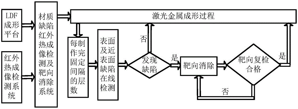
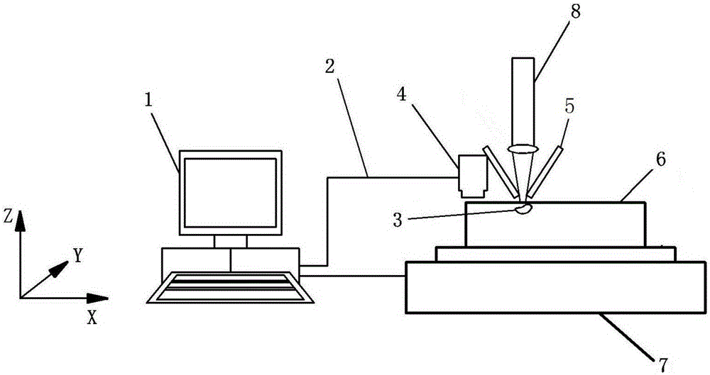
[0035] A TA15 titanium alloy cuboid with a length, width, and height of 100×30×50mm is produced by laser melting deposition forming technology, and the (x, y) coordinate orientation of the lower left corner of the workpiece in the forming plane is (100mm, 100mm). The forming process parameters used are: laser power 300W, scanning speed 10mm / s, powder feeding rate 4.9g / min, laser spot diameter 0.5mm, layer thickness 0.1mm, overlapping rate 40%, scanning method is reciprocating scanning . When making the material, the method of the present invention is used for online detection and targeted elimination of material defects, and the specific steps are as follows:

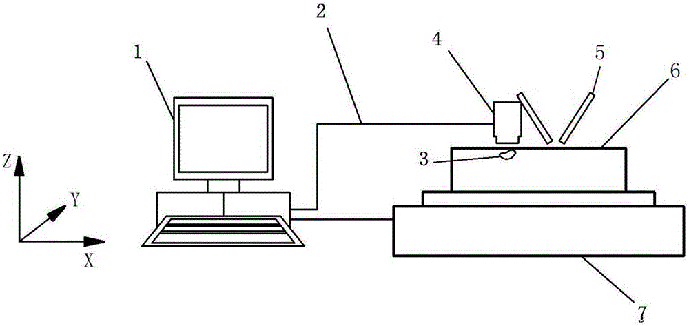
[0036]Step 1, every time 5 layers are finished, the production is suspended, and the computer 1 controls the workbench 7 to move at a constant speed in the horizontal direction at a speed of 20 mm / s, so that the lens of the infrared thermal imaging detector 4 fixed next to the powder feeding nozzle 5 is formed Non-cont...


PUM

PropertyMeasurementUnit
Layer thicknessaaaaaaaaaa

Abstract

The invention discloses a material defect infrared thermal imaging detection and targeted elimination method in laser metal forming. In laser metal forming, after layers with fixed interlayers are produced, a workbench is controlled by a computer to move in the horizontal direction at a constant speed, thus an infrared thermal imaging detection lens can move in the horizontal direction above the imaging plane and carries out non-contact scanning and photo-taking by utilizing the residual heat of metal parts, and then the infrared thermal imaging detection images are analyzed online to calculate the coordinate azimuth of the metal forming plane. The computer control laser beams to target-melt the detected defects so as to eliminate the defects; after laser re-melting, an infrared thermal imaging detector is used to re-examine the metal forming surface to confirm the defect elimination effect. The provided method solves the problems that the defects on micro materials cannot be detected online and eliminated, effectively improves the using performance and service safety of laser formed metal parts, and reduces the risk of fatigue breakage.

Description

technical field [0001] The invention belongs to the technical field of laser metal additive manufacturing, and in particular relates to an infrared thermal imaging detection and targeted elimination method for material defects in laser metal forming. Background technique [0002] Laser metal additive manufacturing is commonly known as laser metal 3D printing, also known as laser metal forming. Since the laser metal additive manufacturing process is a multi-physical field coupling process, the temperature changes drastically during the forming process, and small material defects such as cracks, air bubbles, slag inclusions, interlayer pores, and spheroidization are prone to appear in the formed parts. The range is usually from tens of microns to hundreds of microns. On the one hand, material defects in metal parts may affect the performance of the parts; on the other hand, even if the parts do not affect the performance in the early stage of service, under the long-term acti...

Claims


Application Information

Patent Timeline
IPC IPC(8): G01N25/72B22F3/105
Inventor 解瑞东李涤尘张安峰
Owner XIAN UNIV OF TECH
Why Eureka
Try Eureka