
Method for monitoring secondary pressure plate compulsory locking device and state thereof

A secondary pressure plate and locking device technology, applied in the substation/switch layout details, electrical components and other directions, can solve the problems of troublesome installation, expansion of accidents, poor pressure connection of pressure plate crimping joints, etc., and achieves the effect of cost saving and simple structure

Active Publication Date: 2015-11-11
STATE GRID SHANDONG ELECTRIC POWER +1
View PDF4 Cites 6 Cited by
  • Summary
  • Abstract
  • Description
  • Claims
  • Application Information

AI Technical Summary

Problems solved by technology

[0004] However, the monitoring of the operation information of the protection device by the intelligent dispatching technical support system is limited to prompting whether the protection device is in normal operation, and cannot carry out real-time monitoring and effective control of the actual operation status of the secondary pressure plate that can realize the protection function.
In actual work, due to the needs of operation and maintenance personnel to stop, power transmission operation or maintenance personnel to debug the protection device and adjust the operation mode of the primary system, it is necessary to quickly adjust and change the operation status of the secondary pressure plate of the protection device to realize the primary operation equipment under a specific operation mode. Therefore, the existing monitoring of the operating status of the protection device cannot achieve effective monitoring of the protection device
[0005] The monitoring personnel on duty cannot compare the changes in the operation mode of the primary equipment, and promptly remind the personnel on duty of the substation to adjust the switching and stopping of the secondary pressure plate of the on-site relay protection device of each substation, resulting in protection misoperation due to leakage of the secondary pressure plate. , Refusal to operate causes artificial expansion of accidents from time to time, such as: In April 2008, a 220kV substation caused the No. No electricity in the whole station
In June 2012, a single-phase 330kV line of a 330kV substation was grounded instantaneously, and the protection tripped by mistake. The direct outlet tripped three phases due to mis-injection of the communication triple-trip pressure plate, and the 330kV line was blacked out.
In August 2014, a 330kV substation leapfrogged and tripped due to missing switch outlet pressure plate and failure of the pressure plate, resulting in no electricity in the 330kV substation
Since the purpose of indirect locking of the secondary pressure plate is only realized, the real mandatory locking cannot be realized. In this way, for the staff who are not familiar with the working principle of the protection device, after the secondary pressure plate is mismoved, although the pressure plate state sensor shows that the position state is correct, However, the crimping of the pressure plate crimping head is not firm, and the protection device cannot operate normally.
[0007] At the same time, when installing and debugging, it is necessary to install a pressure plate status collector on each protective screen, and to wire each pressure plate, which is troublesome to install and cannot be easily installed under the normal operating state of the protective pressure plate

Method used


Image

  • Method for monitoring secondary pressure plate compulsory locking device and state thereof
  • Method for monitoring secondary pressure plate compulsory locking device and state thereof
  • Method for monitoring secondary pressure plate compulsory locking device and state thereof

Examples


Embodiment 1

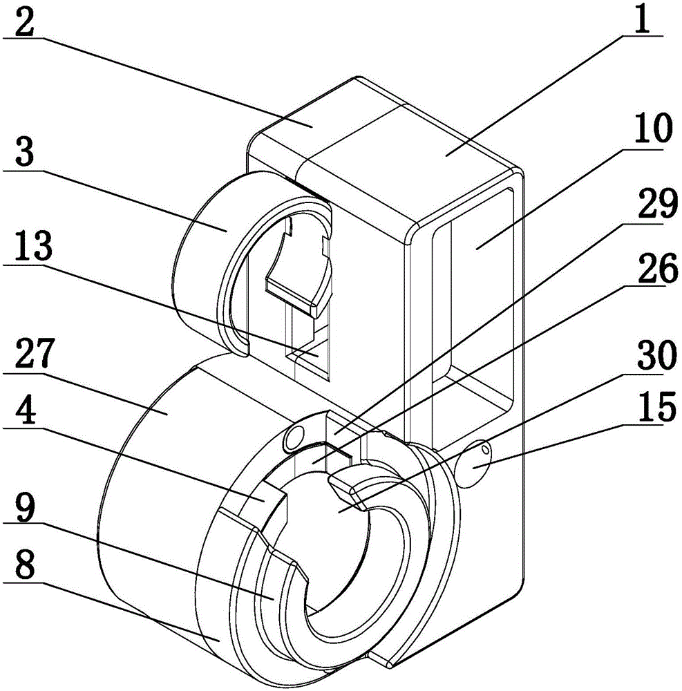
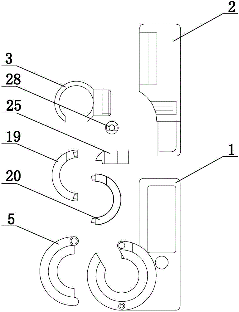
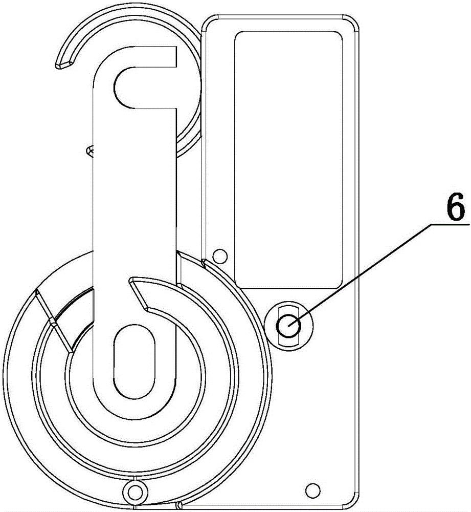
[0056]Embodiment 1: The secondary pressure plate forced locking device according to the present invention includes a casing, and also includes the following components: upper casing 1, lower casing 2, static contact ferrule 3, internal rotating shaft 4 of ferrule, and locking sleeve The left half of the base 5, the internal lock 6 and the RFID chip 7, the upper shell 1 is provided with the moving contact lock sleeve 8, the rotation track groove guard plate 9, the RFID chip installation groove 10 and the groove 11, the rotation track groove Guard plate 9 is located in moving contact lock sleeve 8, and is fixedly connected, and RFID code chip installation groove 10 side is provided with keyhole 15; Both lower shell 2 and upper shell 1 are provided with screw holes, and are connected by bolts. The upper shell 1 and the lower shell 2 are fixedly connected in the screw hole, and the lower shell 2 is provided with a groove B12 corresponding to the groove 11 of the upper shell 1, and ...

Embodiment 2

[0057] Embodiment 2: On the basis of the structure described in Embodiment 1, the static contact ferrule moving groove 13 includes a slider sliding track and a connecting block sliding track, the section of the slider sliding track is adapted to the slider section, and the connecting block sliding track The cross-section is less than the cross-section of the slide block, so that the slide block 18 can only move in the slide block sliding track, but cannot pass the connecting block sliding track.

Embodiment 3

[0058] Embodiment 3: On the basis of the structure described in Embodiment 2, the locking sleeve clamping base 27 is set on the moving contact base of the pressure plate, the moving contact lock sleeve 8 is set on the moving contact of the pressure plate, and the pressure plate connecting piece Pass through the slot 26 of the connecting piece.


PUM


Abstract

The invention provides a method for monitoring a secondary pressure plate compulsory locking device and the state thereof, and belongs to the field of apparatuses for monitoring the states of put-into-use and out-of-use of secondary pressure plate of an electric power system. The invention involves the secondary pressure plate compulsory locking device, a scheduling main station server, an anti-error host and a computer key. A pressure plate can be compulsorily locked, and completely broken apart, and the states of put-into-use and out-of-use of the pressure plate are effectively recorded. The secondary pressure plate compulsory locking device can be installed while a secondary pressure plate is under an operating state, and on-line monitoring the states of put-into-use and out-of-use of relay protective pressure plate of all stations at the scheduling main station can be realized through telecommunication.

Description

technical field [0001] The invention provides a forced locking device for a secondary pressing plate and a state monitoring method thereof, and belongs to the field of monitoring devices for switching on and off of a secondary pressing plate in a power system. Background technique [0002] The secondary equipment of the power system is an important part of the safe operation of the power grid. It monitors, measures, operates and controls the primary equipment and plays a protective role. The relay protection device in the secondary equipment is an important guarantee for the safe and stable operation of the primary equipment in the power grid. Among the existing protection devices, the secondary pressure plate is used to switch on and off the function of the protection device and the key to the trip outlet circuit. The pressure plate is correctly put in, Whether to exit or not is directly related to whether the protection device can operate correctly, and the fault can be re...

Claims


Application Information

Patent Timeline
IPC IPC(8): H02B1/00
Inventor 季素云冯忠奎贾栋尚刘兴华阎炳水乔恒耿宁杨静许小滔李垚张子晗崔川梁珊珊张阳于洋林英吕东飞巩方伟席文娣窦维亮刘冰刘新生张元标李强王讯孙磊于俊海胡博邻王磊谢德杰姚树汾刘达王明波王天勇李凯王欣
Owner STATE GRID SHANDONG ELECTRIC POWER
Learn More