A transmission for an electric vehicle

A technology of electric vehicles and transmissions, applied in electric vehicles, electric components, electromechanical transmissions, etc., can solve the problems of high price, poor speed regulation performance of AC induction motors, and unsatisfactory performance, and achieve good speed regulation, compact structure, and good performance. The effect of vibration isolation

Inactive Publication Date: 2018-03-30
GUANGDONG UNIV OF TECH
View PDF5 Cites 0 Cited by
  • Summary
  • Abstract
  • Description
  • Claims
  • Application Information

AI Technical Summary

Problems solved by technology

AC induction motors have the advantages of simple structure, good reliability, low cost, and long life, but the speed regulation performance of AC induction motors is poor, and the cost of the motor controller is much higher than the motor itself, which limits the use of low-cost AC induction motors in electric motors. For automotive applications, only expensive permanent magnet synchronous motors or switched reluctance motors can be used. Although these two motors have the advantages of high power density, compact structure, and small size, their high prices cannot meet the needs of current consumption in my country. Large demand from consumers for cheap, practical electric vehicles

Method used


Image

  • A transmission for an electric vehicle
  • A transmission for an electric vehicle
  • A transmission for an electric vehicle

Examples


Embodiment

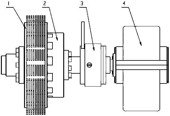
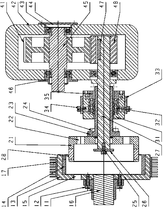
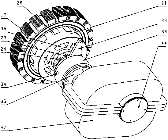
[0016] The structure diagram of the present invention is as figure 1 , 2 , 3, the electric vehicle transmission of the present invention includes a permanent magnet speed regulating part and a reduction box 4, and the permanent magnet speed regulating part includes a cylindrical conductor rotor 1, a cylindrical permanent magnet rotor 2 and a speed regulating mechanism 3 three Part, the main body of the cylindrical conductor rotor 1 includes a conductor drum 13, an inner conductor 14 and an active flange 11, wherein the conductor drum 13 is connected to the input shaft 16 through the active flange 11, and the active flange 11 is set on the input shaft 16, and the active flange 11 is connected to the conductor drum 13, the inner wall of the conductor drum 13 is provided with a layer of inner conductor 14, the main body of the cylindrical permanent magnet rotor 2 includes a permanent magnet drum 21, a permanent magnet 28 And the driven flange 23, wherein one end of the rotating ...


PUM


Abstract

The invention relates to a transmission for an electric vehicle. The transmission comprises a permanent magnetic speed adjustment part and a reduction gearbox; the permanent magnetic speed adjustment part includes a cylinder-shaped conductor rotor, a cylinder-shaped permanent magnetic rotor and a speed adjustment mechanism; the cylinder-shaped conductor rotor includes a conductor rotating cylinder, an inner-layer conductor and a driving flange; the conductor rotating cylinder is connected with the input shaft through the driving flange; the driving flange sleeves the input shaft; the driving flange is connected with the conductor rotating cylinder; the cylinder wall at the inner side of the conductor rotating cylinder is provided with the inner-layer conductor; the cylinder-shaped permanent magnetic rotor includes a permanent magnetic rotating cylinder, permanent magnets and a driven flange; two ends of a rotating shaft are supported on the reduction gearbox and the permanent magnetic rotating cylinder; the driven flange sleeves the rotating shaft; the driven flange is connected with the permanent magnetic rotating cylinder; the permanent magnets are embedded into the permanent magnetic rotating cylinder along the circumferential direction of the permanent magnetic rotating cylinder; a gap is left between the outer sides of the permanent magnets and the inner wall of the inner-layer conductor; and the speed adjustment mechanism includes an inner circular sleeve, an outer circular sleeve and a slider; the inner circular sleeve sleeves the outer circumferential surface of the driven flange; and the slider arranged on the outer circular sleeve is installed in a slide groove in the inner circular sleeve. The transmission for the electric vehicle of the invention is advantageous in excellent vibration isolation and damping effects, and smooth operation.

Description

technical field [0001] The invention relates to a transmission for an electric vehicle, which belongs to the transformation technology of the transmission for an electric vehicle. Background technique [0002] In recent years, under the background of emphasizing energy conservation and environmental protection, new energy vehicles represented by electric vehicles are a development trend in the automotive industry. One of the current bottlenecks in the development of electric vehicles is the high technical requirements and high price of the motor. DC motor is the earliest electric motor used in electric vehicle drive system. It has the advantages of smooth speed regulation, simple control and mature technology. However, DC motor needs commutator and brushes. The efficiency is low, the price is high, and the weight and volume are large. Therefore, the application of DC motors in electric vehicles is limited and is being replaced by AC induction motors, permanent magnet synch...

Claims


Application Information

Patent Timeline
Patent Type & Authority Patents(China)
IPC IPC(8): H02K49/10H02K49/04H02K51/00H02K7/11H02K7/116B60K17/02
CPCY02T10/64
Inventor 阳林田硕叶磊钟云耀陈楠楠万婷婷
Owner GUANGDONG UNIV OF TECH
Why Eureka
Try Eureka