Soft start and closed-loop control method of pulse generating circuit

A technology for generating circuits and closed-loop control, applied in electrical components, output power conversion devices, etc., can solve the problems of reducing the dust collection area, limitation, and lack of practicality of the dust collector, and achieve increased stability and anti-interference ability. The effect of avoiding shock

Inactive Publication Date: 2015-11-11
XI AN JIAOTONG UNIV +1
View PDF5 Cites 4 Cited by
  • Summary
  • Abstract
  • Description
  • Claims
  • Application Information

AI Technical Summary

Problems solved by technology

This method realizes the superposition of high-voltage direct current and high-voltage pulse, and has the advantages of overcoming the back corona phenomenon, improving the dust collection efficiency, and reducing the dust collection area of ​​the dust collector, but it also has the following disadvantages: (1) The power supply involved in this method The structure is too abstract, there is no specific power supply structure, and the implementation is difficult. For example, the adjustable range of high-voltage pulse amplitude is 1kV to 1000kV, and the adjustable range of pulse frequency is 1Hz to 1000kHz. The high-voltage DC voltage only needs tens of kilovolts, and the frequency of high-voltage pulses is only a few hundred Hz, which is not practical.
(2) The parameter setting is too ideal. For example, 1kV and 1000kV belong to completely different voltage levels, and the corresponding insulation levels are also different. It is difficult to make a high-voltage DC source adjustable from 1kV to 1000kV, and it is impossible to control the high-voltage DC of the existing dust collector. Power Supply for Low-Cost Retrofit
Therefore, based on the above shortcomings, the specific application of this method is limited.

Method used


Image

  • Soft start and closed-loop control method of pulse generating circuit
  • Soft start and closed-loop control method of pulse generating circuit
  • Soft start and closed-loop control method of pulse generating circuit

Examples


Embodiment Construction

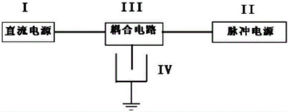
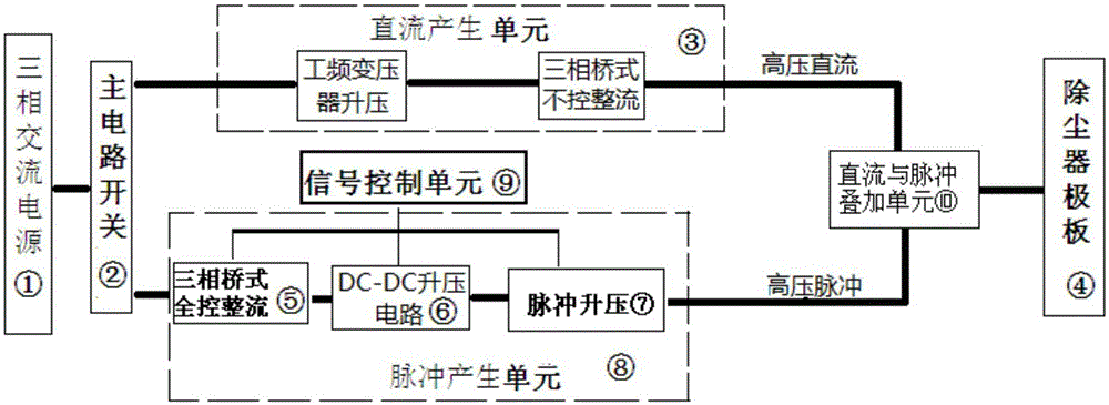
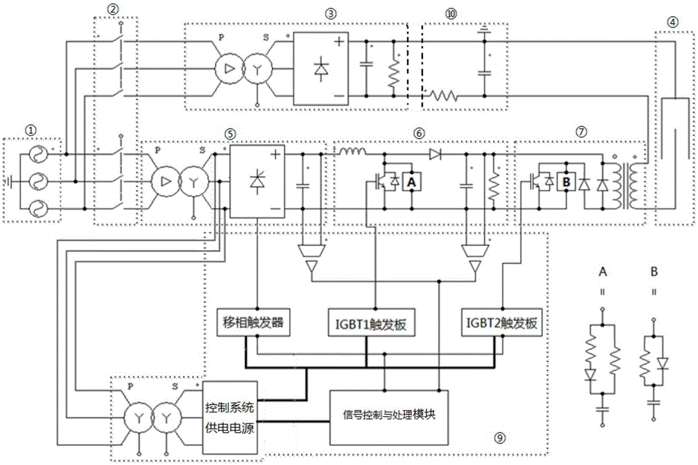
[0021] Such as figure 2 As shown, a DC pulse power supply scheme for electrostatic precipitator, the designed power supply includes a main circuit switch ② connected to the three-phase AC power ①, a DC generating unit ③ connected to the main circuit switch and a pulse generating unit ⑧ , the pulse generation unit is connected to a signal control unit ⑨, the output of the DC generation unit and the pulse generation unit is connected to the dust collector plate ④ through a DC and pulse superposition unit ⑩. Among them, the DC generation unit is composed of a power frequency transformer step-up module and a three-phase bridge uncontrolled rectification module in series; the pulse generation unit is sequentially composed of a three-phase bridge full-control rectification module ⑤, a DC-DC step-up circuit ⑥, a pulse step-up Module ⑦ constitutes. After the three-phase AC power supply is switched by the main circuit, one path is boosted and rectified by the DC generating unit to ob...


PUM


Abstract

The invention discloses a soft start and closed-loop control method of a pulse generating circuit, wherein the pulse generating circuit is a pulse generating unit controlled by a signal control unit in an electrostatic dust collection power supply and is composed of a three-phase bridge full-controlled rectifier module, a DC-DC boosted circuit and a pulse boosting module; the output of the signal control unit is divided into three paths, which are separately connected with the three-phase bridge full-controlled rectifier module, the DC-DC boosted circuit and the pulse boosting module; while starting the three-phase bridge full-controlled rectifier module and the DC-DC boosted circuit, the signal control unit provides a soft start signal and a PI adjusting signal and using a relative small value as the control signal after comparing so as to realize the soft start of the corresponding module; while the module output voltage is gradually risen to certain value, the PI output value is reduced. Only by setting the final value of the soft start signal to be more than a prospective PI output value, the PI output provides control for the corresponding module so as to realize the closed-loop control.

Description

technical field [0001] The invention relates to a power supply control technology, in particular to a high-voltage pulse control method for an electrostatic precipitator power supply. Background technique [0002] Electrostatic dust removal is a commonly used dust removal method in modern industrial systems, and it is also an important means of controlling air pollution. At present, the electrostatic precipitator method adopted by most enterprises is to use high-voltage direct current as the power supply of the precipitator. In this power supply mode, the equivalent capacitance effect of the dust layer will cause the back corona phenomenon, resulting in a decrease in dust removal efficiency, and for dust particles with a particle size of less than 0.1 μm, the dust removal efficiency is very low. With the continuous improvement of national environmental protection requirements, the requirements for exhaust emissions of enterprises have also increased. The traditional electro...

Claims


Application Information

Patent Timeline
Patent Type & Authority Applications(China)
IPC IPC(8): H02M9/06H02M1/36
Inventor 贺博王燕齐以年赵青松孟永鹏龚晓宏吴晓明
Owner XI AN JIAOTONG UNIV
Why Eureka
Try Eureka