Signal modulation method and signal rectification and modulation device

A technology of signal modulation and modulation control, applied in the direction of circuit devices, pulse amplitude modulation, output power conversion devices, etc., can solve the residual voltage of the gate, the inability to completely reach zero potential, and the inability of the lower bridge switch component B2 to be completely disconnected, etc. question

Active Publication Date: 2015-11-11
FU TONG TECH
View PDF5 Cites 11 Cited by
  • Summary
  • Abstract
  • Description
  • Claims
  • Application Information

AI Technical Summary

Problems solved by technology

However, if figure 2 As shown in the waveform W2_2 of , during the modulation period (that is, when the gate signals of the switch components A6 and B6 are at high potential), the gate of the lower bridge switch component B2 still has a residual voltage, which cannot completely reach zero potential, causing the lower bridge switch component B2 cannot be completely disconnected, causing unnecessary power consumption during modulation

Method used


Image

  • Signal modulation method and signal rectification and modulation device
  • Signal modulation method and signal rectification and modulation device
  • Signal modulation method and signal rectification and modulation device

Examples


Embodiment Construction

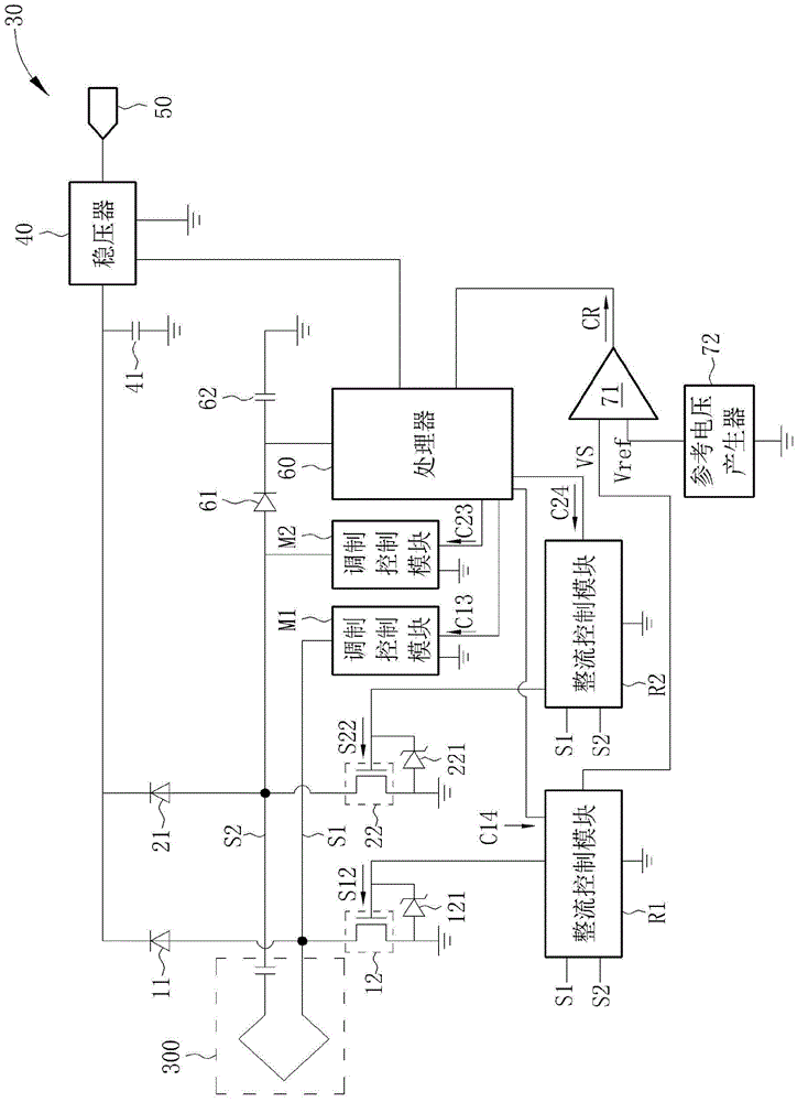
[0059] Please refer to image 3 , image 3 It is a schematic diagram of a power receiving module 30 according to an embodiment of the present invention. The power receiving module 30 can be used in an inductive power supply for receiving power from a corresponding power supply module in the inductive power supply. like image 3 As shown, the power receiving module 30 includes an induction coil 300, rectification diodes 11 and 21, rectification transistors 12 and 22, protection diodes 121 and 221, rectification control modules R1 and R2, modulation control modules M1 and M2, and a reference voltage generator 72 . A comparator 71 , a processor 60 , a voltage regulator 40 and a power output terminal 50 . In addition, in order to provide a stable working voltage for the processor 60 , the power receiving module 30 further includes a rectifier diode 61 and a filter capacitor 62 , which are arranged at the power input end of the processor 60 . In order to provide stable input po...


PUM


Abstract

A signal modulation method for a receiving-end module of an induction type power supply system includes configuring a plurality of modulation periods corresponding to a modulation signal; performing modulation on a first terminal of an induction coil of the receiving-end module during the i<SP>th</SP>modulation period among the plurality of modulation periods, wherein i is an odd number; and performing modulation on a second terminal of the induction coil of the receiving-end module during the j<SP>th</SP>modulation period among the plurality of modulation periods, wherein j is an even number; wherein the second terminal does not undergo modulation when the first terminal is being modulated, and the first terminal does not undergo modulation when the second terminal is being modulated. The present invention also provides a signal rectification and modulation device.

Description

technical field [0001] The invention relates to a signal modulation method and a signal rectification and modulation device, in particular to a staggered signal modulation method and a signal rectification and modulation device. Background technique [0002] In the inductive power supply, in order to operate safely, it is necessary to confirm that the induction area on the power supply coil is the correct power receiving device at the supply end, and only transmit power when the power can be received. In order for the power supply end to identify the power receiving device Whether the terminal is a correct power receiving device needs to be identified by transmitting a data code. The transmission of the data code is to drive the power supply coil to generate resonance through the power supply end, and transmit the electromagnetic energy to the power receiving end for power transmission. When the power receiving end receives power, the impedance state on the receiving coil ca...

Claims


Application Information

Patent Timeline
Patent Type & Authority Applications(China)
IPC IPC(8): H03K7/02H02M7/217
CPCH02J50/12H02J50/80
Inventor 蔡明球詹其哲
Owner FU TONG TECH
Why Eureka
Try Eureka