Portable Eye Pressurizer
A portable, pressurizer technology, applied in the field of medical devices, can solve the problems of difficult massage volume, increase the burden of patients and clinical work, etc., and achieve the effects of convenient carrying and adjustment, good application value, and easy control.
- Summary
- Abstract
- Description
- Claims
- Application Information
AI Technical Summary
Problems solved by technology
Method used
Image
Examples
Embodiment 1
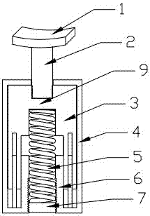
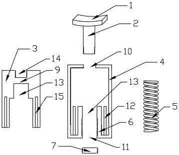
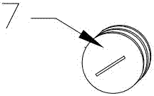
[0025] Such as Figure 1 to 3 As shown, a portable eye pressurizer includes a pressurizing arc with a press rod 2, a press rod sleeve 3, a spring 5, a fine adjustment bolt 7 and a housing 4; the upper and lower ends of the housing 4 are respectively provided with first The notch 10 and the second notch 11, and the second notch 11 is provided with a folding edge 6 extending inward of the shell, and the folding edge 6 is provided with a thread; the inner side of the front and rear two side walls of the shell 4 is provided with longitudinal guide posts 12 , The guide post 12 is provided in the space enclosed by the flange 6 and the side wall of the housing 4;
[0026] The pressing rod sleeve 3 is arranged in the housing 4, and the housing 4 is matched to form a cavity 13, and a baffle 9 is provided between the cavity 13 and the first notch 10. The top of the pressing rod cover 3, the baffle 9 is provided with a threaded groove 14 above; the lower end of the pressure rod sleeve 3 is...
Embodiment 2
[0030] Such as Figure 4 As shown, the structure of the second embodiment is similar to that of the first embodiment, and the difference is that: the upper and lower ends of the outer side of the side wall of the housing 4 are both provided with ribs 16. Four connecting parts 17 with connecting holes 18 are symmetrically provided on the side walls of the housing 4, and a rope can be passed through the connecting holes 18 to fix the presser to the head and reduce the force of the hands to facilitate Precise quantitative control of products. In addition, a washer 19 is provided between the fine adjustment bolt 7 and the spring 5. The lower end of the fine-tuning bolt 7 is connected to the adjusting knob 8. The maximum displacement of the downward movement of the adjusting knob 8 does not exceed the bottom of the housing 4. That is, the adjusting knob 8 is hidden in the housing 4, and it is not easy to touch and cause errors when carried.
PUM
 Abstract
Description
Claims
Application Information
 - R&D
- Intellectual Property
- Life Sciences
- Materials
- Tech Scout
- Unparalleled Data Quality
- Higher Quality Content
- 60% Fewer Hallucinations
Browse by: Latest US Patents, China's latest patents, Technical Efficacy Thesaurus, Application Domain, Technology Topic, Popular Technical Reports.
© 2025 PatSnap. All rights reserved.Legal|Privacy policy|Modern Slavery Act Transparency Statement|Sitemap|About US| Contact US: help@patsnap.com


