
Device for remedying soil contaminated by volatile organic compounds

A technology of volatile organic compounds and polluted soil, applied in the restoration of polluted soil, etc., can solve the problems of low thermal energy utilization rate, high repair cost, poor sealing performance, etc., and achieve high thermal energy utilization rate, low repair cost and good sealing performance Effect

Active Publication Date: 2015-11-18
SHANGHAI RES INST OF CHEM IND
View PDF6 Cites 10 Cited by
  • Summary
  • Abstract
  • Description
  • Claims
  • Application Information

AI Technical Summary

Problems solved by technology

The repair equipment for volatile polluted soil described in this patent has a simple structure and combines chemical methods to treat tail gas. It is suitable for soil polluted by high concentrations of volatile pollutants, but its thermal energy utilization rate is low and the repair cost is high.
[0008] According to the above analysis, it can be found that the current problems of thermal desorption devices for contaminated soil are mainly two aspects: low thermal energy utilization rate and poor sealing performance. Secondary pollution caused by leakage of pollutants into the atmosphere

Method used


Image

  • Device for remedying soil contaminated by volatile organic compounds
  • Device for remedying soil contaminated by volatile organic compounds
  • Device for remedying soil contaminated by volatile organic compounds

Examples


Embodiment 1

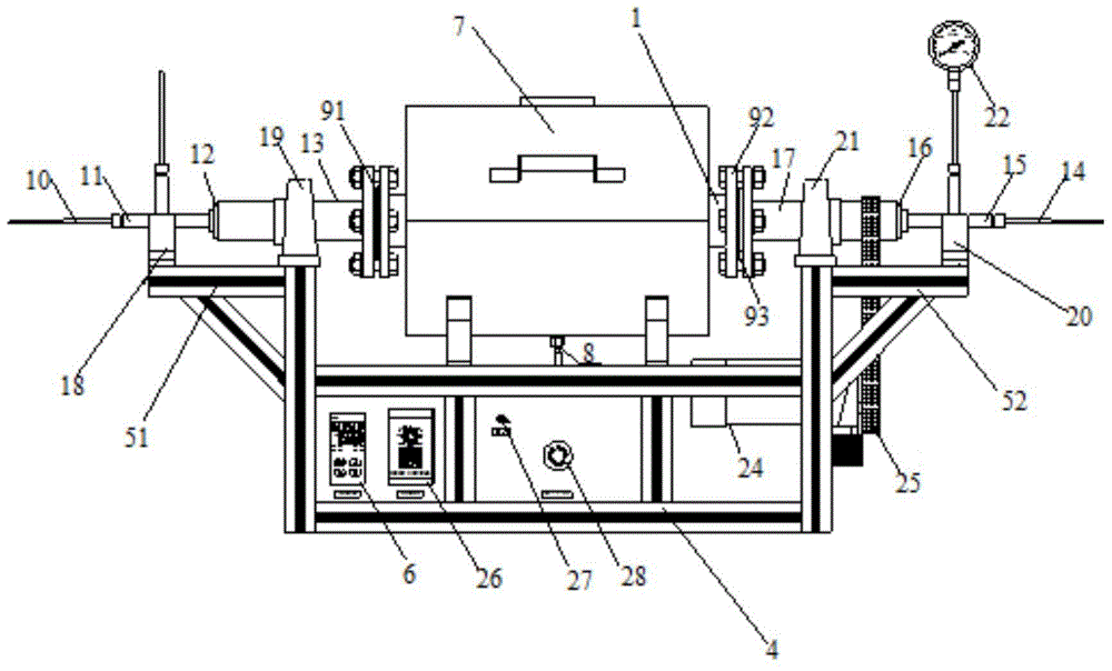
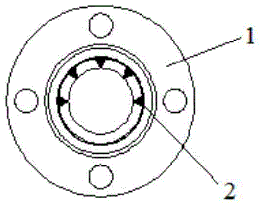
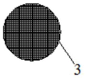
[0046] Such as figure 1 , 3 As shown in and 4, a device for remediation of soil contaminated by volatile organic compounds, including a heating control system, a thermal desorption tube 1 arranged in the heating control system, a rotation control system connected to the thermal desorption tube 1 in transmission, and The inlet pipeline system and the gas outlet pipeline system arranged at both ends of the thermal desorption tube 1, the inner wall of the thermal desorption tube 1 is provided with a plurality of tooth-shaped lifting plates 2, and the thermal desorption tube 1 is connected with the gas outlet pipeline system One end is also provided with a porous dust filter 3, and the outlet pipeline system is connected with the external exhaust gas absorption system. There are a first support 51 and a second support 52 .

[0047] Such as figure 2 As shown, there are five tooth-shaped lifting plates 2 in total, and they are arranged in a semicircle on the inner wall of the th...

Embodiment 2

[0061] In this embodiment, there are 6 tooth-shaped lifting plates 2 in total, and they are arranged in a semicircle on the inner wall of the thermal desorption tube 1 . All the other are with embodiment 1.

Embodiment 3

[0063] In this embodiment, there are 8 tooth-shaped lifting plates 2 in total, and they are arranged in a semicircle on the inner wall of the thermal desorption tube 1 . All the other are with embodiment 1.


PUM


Abstract

The invention relates to a device for remedying soil contaminated by volatile organic compounds. The device for remedying the soil contaminated by the volatile organic compounds comprises a heating control system, a thermal desorption pipe arranged in the heating control system, a rotation control system in transmission connection with the thermal desorption pipe, an air inlet pipeline system and an air outlet pipeline system, wherein the air inlet pipeline system and the air outlet pipeline system are arranged at the two ends of the thermal desorption pipe. A plurality of tooth-shaped shoveling plate are arranged on the inner wall of the thermal desorption pipe. A multi-hole dust filter screen is further arranged at the end, connected with the air outlet pipeline system, of the thermal desorption pipe. The air outlet pipeline system is communicated with an external tail gas absorption system. Compared with the prior art, the device is simple and compact in overall structure and good in sealing performance; by the adoption of the heating control system and the rotation control system, automatic control over heating and rotation can be achieved; operation is easy, and working efficiency is greatly improved; the device is economical and practical; the heat energy utilization rate is high, and the remediation cost is greatly reduced.

Description

technical field [0001] The invention belongs to the technical field of environmental protection and relates to a device for repairing soil polluted by volatile organic compounds. Background technique [0002] In recent years, with the rapid development of modern industry and the acceleration of urbanization, there have been a large number of chemical enterprises that have been relocated or will be shut down in my country. However, due to the lack of awareness of environmental protection and poor management of these enterprises in the past production and operation, a large amount of toxic and harmful substances, especially organic pollutants, entered the soil, causing serious site soil pollution problems. [0003] Most of the organic pollutants in the soil are volatile, and have "teratogenic", "carcinogenic", and "mutagenic" effects, which seriously threaten human health and environmental safety. In recent years, due to the concentrated emergence of environmental accidents a...

Claims


Application Information

Patent Timeline
IPC IPC(8): B09C1/00
Inventor 李森周玉强姜达强张杨张宏玲商照聪罗勇吴向阳
Owner SHANGHAI RES INST OF CHEM IND
Learn More