Welding device for side sealing plate barb of switch cabinet

A welding device and switchgear technology, applied in auxiliary devices, welding equipment, welding equipment, etc., can solve the problems of laborious welding and poor welding quality, and achieve the effect of good connection strength and good quality consistency

Inactive Publication Date: 2015-11-18
张进
View PDF11 Cites 49 Cited by
  • Summary
  • Abstract
  • Description
  • Claims
  • Application Information

AI Technical Summary

Problems solved by technology

[0003] The invention provides a barb welding device for the side sealing plate of the switch cabinet that does not need to be manually fixed and has a good vibration isolation effect, which solves the problem of manually fixing the weld parts and welding the barbs in the switch cabinet to the column The problem of laborious welding and poor welding quality

Method used


Image

  • Welding device for side sealing plate barb of switch cabinet
  • Welding device for side sealing plate barb of switch cabinet
  • Welding device for side sealing plate barb of switch cabinet

Examples


Embodiment 1

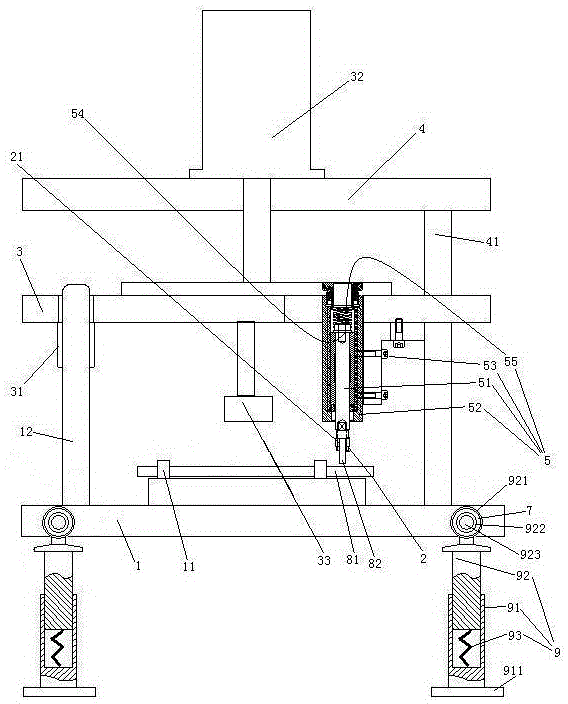
[0028] Embodiment one, see figure 1 , a barb welding device for the side sealing plate of a switchgear, including a support column 9, a lower seat 1, a conductive block 33, a suspension plate 3 and an upper seat 4 arranged from bottom to top.

[0029] There are four supporting columns 9. The support column 9 includes a lower section 91 and an upper section 92 . The lower end of the lower section 91 is provided with a mounting base 911 . The upper end of the lower section 91 is slidably sleeved on the lower end of the upper section 92 . The lower section 81 is provided with a damping spring 93 supporting the upper section 92 . The upper end of the upper section 92 is provided with a connecting ring 921 . An inner ring 922 passes through the connecting ring 921 . The inner ring 922 is connected with the connecting ring 921 through the rubber ring 7 . The inner ring 922 is pierced with connecting pins 923 . The connecting pin 923 is connected with the lower end of the lowe...

Embodiment 2

[0042] Embodiment two, the difference with embodiment one is:

[0043] see Figure 9 , The supporting column 9 is also provided with a drive mechanism 6 . The inner ring 922 is rotatably connected to the rubber ring 7 , and the rubber ring 7 is fixedly connected with the connecting ring 921 .

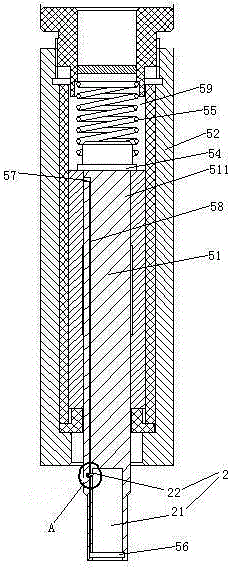
[0044] The drive mechanism 6 includes a ratchet 61 , a pawl 62 for driving the ratchet, and a drive lever 63 . The ratchet 61 is coaxially connected with the inner ring 922 . The ratchet 61 is integrated with the inner ring 922 . The pawl 62 is fixedly connected to one end of the driving rod 63 . The upper section 92 is provided with a sliding hole 924 . The other end of the driving rod 63 can slide through the sliding hole 924 two-dimensionally. The lower end of the drive rod 63 is slidably hooked to the lower section 91 along the radial direction of the connecting ring 921 (see figure 2 ) and connected with the next paragraph. The driving rod 63 is provided with a storage hol...


PUM


Abstract

The invention relates to the technical field of manufacturing of low-voltage drawer-type switch cabinets and discloses a welding device for a side sealing plate barb of a switch cabinet. The welding device comprises an electric welding machine, a spot welding gun, supporting pillars, a lower base, an electric conduction block, a suspending plate and an upper seat. The electric welding machine is provided with two electrodes, and the spot welding gun is connected with one of the electrodes. Clamps are arranged on the lower seat, and the suspending plate is connected with the upper seat through an air cylinder. The electric conduction block is connected to the suspending plate. The electric conduction block is electrically connected with the other electrode. The spot welding gun is connected to the suspending plate and is provided with a barb fixing structure. The supporting pillars comprise damper springs, upper sections and lower sections, wherein the upper sections and the lower sections are sleeved together. The upper ends of the upper sections are provided with connecting rings, inner rings are arranged in the connecting rings in a penetrating mode, the inner rings and the connecting rings are connected together through rubber rings, and connecting pins connected to the lower seat are arranged in the inner rings in a penetrating mode. The welding device has the advantages that a welded part does not need to be fixed manually, and the vibration isolation effect is good; the problems that much effort is cost in welding and the welding quality is poor due to welding by manually fixing the welded part are solved.

Description

technical field [0001] The invention relates to the technical field of low-voltage withdrawable switch cabinet manufacturing, in particular to a barb welding device for a side sealing plate of a switch cabinet. Background technique [0002] The low-voltage withdrawable switchgear has the characteristics of breaking, high connecting capacity, good dynamic and thermal stability, flexible electrical scheme, convenient combination, strong serial practicability, novel structure, and high protection level. It is welcomed by the majority of users and is widely used in The power distribution centers of power plants, substations, factories and mines, high-rise buildings, and motor control centers are used as low-voltage complete power distribution devices for power distribution, centralized control of motors, and reactive power compensation in power generation and power supply systems. A low-voltage withdrawable switchgear is disclosed in the patent document with the Chinese patent n...

Claims


Application Information

Patent Timeline
Patent Type & Authority Applications(China)
IPC IPC(8): B23K11/11B23K11/31B23K11/36B23K37/04
CPCB23K11/11B23K11/314B23K11/36B23K37/0435
Inventor 张进
Owner 张进
Why Eureka
Try Eureka