
Automatic cotton kneading device

An automatic, cotton board technology, applied in the direction of fabric kneading/softening, textile and papermaking, fabric surface trimming, etc., can solve the problems of high production cost, low work efficiency, uneven batting, etc., and achieve low production and processing costs. , The effect of strong work stability and easy production and processing

Inactive Publication Date: 2015-11-18
HENAN XINPUFENG COTTON GIN TECH CO LTD
View PDF5 Cites 5 Cited by
  • Summary
  • Abstract
  • Description
  • Claims
  • Application Information

AI Technical Summary

Problems solved by technology

[0002] Cotton needs to be kneaded in the production process of cotton tires. The equipment used for the process of kneading cotton is relatively complicated, and even many production and processing factories are still using the method of manually kneading cotton
The existing mechanical equipment has high manufacturing cost and poor working stability, while the manual kneading method has low work efficiency. On the other hand, due to the limitation of operation, manual kneading can only knead partial cotton tires, which will eventually lead to Partial unevenness of the formed batt
[0003] For modern machinery, multiple drive motors are generally used in the prior art to drive together, and the coordination between the motors is highly required. When one drive motor fails, other motors may be affected to a certain extent. On the other hand, existing equipment The production cost is relatively high, and the processing and production is difficult, so it cannot cater to the market

Method used


Image

  • Automatic cotton kneading device
  • Automatic cotton kneading device
  • Automatic cotton kneading device

Examples


Embodiment 1

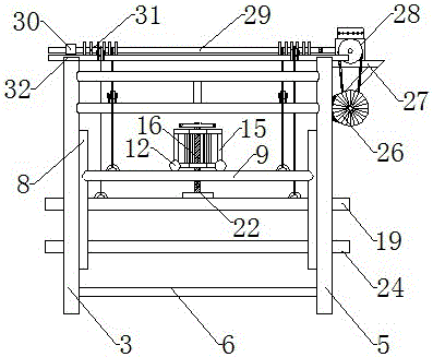
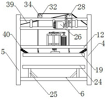
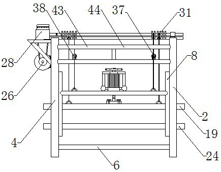
[0028] like figure 1 -Shown in 12: a kind of automatic kneading cotton device, comprises main frame 1, and described main frame 1 is the rectangular frame body that is built by steel pipe, and it comprises the pillar A2 that is arranged on four azimuths, pillar B3, pillar C4 and The pillar D5, between the pillar A2 and the pillar B3, between the pillar B3 and the pillar D5, between the pillar D5 and the pillar C4, between the pillar C4 and the pillar A2, is provided with a supporting pillar 6 near the bottom of the main frame 1, Between the pillar A2 and the pillar B3, between the pillar B3 and the pillar D5, between the pillar D5 and the pillar C4, between the pillar C4 and the pillar A2, there is a support frame 7 near the top of the main frame 1, which is characterized in that A slide rail 8 is arranged on the opposite side wall of the pillar A2 and the pillar C4, a slide rail 8 is also arranged on the opposite side wall of the pillar B3 and the pillar D5, and the main fram...

Embodiment 2

[0032] like figure 1 -Shown in 12: a kind of automatic kneading cotton device, comprises main frame 1, and described main frame 1 is the rectangular frame body that is built by steel pipe, and it comprises the pillar A2 that is arranged on four azimuths, pillar B3, pillar C4 and The pillar D5, between the pillar A2 and the pillar B3, between the pillar B3 and the pillar D5, between the pillar D5 and the pillar C4, between the pillar C4 and the pillar A2, is provided with a supporting pillar 6 near the bottom of the main frame 1, Between the pillar A2 and the pillar B3, between the pillar B3 and the pillar D5, between the pillar D5 and the pillar C4, between the pillar C4 and the pillar A2, there is a support frame 7 near the top of the main frame 1, which is characterized in that A slide rail 8 is arranged on the opposite side wall of the pillar A2 and the pillar C4, a slide rail 8 is also arranged on the opposite side wall of the pillar B3 and the pillar D5, and the main fram...


PUM


Abstract

The invention relates to an automatic cotton kneading device including a main frame; the main frame is constructed by a structural steel framework; opposite side walls of a pillar A of the main frame and a pillar D of the main frame and opposite side walls of a pillar B of the main frame and a pillar D of the main frame are each provided with a slide rail; the slide rails are provided with a lifting frame; the lifting frame includes a sliding horizontal column A, a sliding horizontal column B and a ladder-shaped frame; the ladder-shaped frame is provided with a steel frame and a drive motor B; the center of the steel frame is provided with a transmission shaft; the drive motor B is connected with the transmission shaft by a belt; the lower end of the transmission shaft is connected with a connection shaft; the lower end of the connection shaft is connected with a cotton kneading plate; a cotton supporting plate is arranged below the cotton kneading plate; the right side of the main frame is provided with a drive motor A and a speed reduction motor; the speed reduction motor is connected with a wire coiling shaft; the top of the main frame is also provided with a wire tapping shaft; the wire coiling shaft is provided with a turn ring; the turn ring is wound with eight steel wire ropes; the eight steel wire ropes are respectively fixed on hanging ears of the sliding horizontal column A, hanging ears of the sliding horizontal column B and hanging ears of the cotton kneading plate.

Description

technical field [0001] The invention belongs to the technical field of textile machinery, in particular to a cotton kneading device, in particular to an automatic cotton kneading device. Background technique [0002] Cotton needs to be kneaded in the production process of cotton tires, and the equipment used for the process of kneading cotton is relatively complicated, and even many production and processing factories are still using the method of manually kneading cotton. The existing mechanical equipment has high manufacturing cost and poor working stability, while the manual kneading method has low work efficiency. On the other hand, due to the limitation of operation, manual kneading can only knead partial cotton tires, which will eventually lead to The phenomenon that the formed cotton batt is locally uneven. [0003] For modern machinery, multiple drive motors are generally used in the prior art to drive together, and the coordination between the motors is highly requ...

Claims


Application Information

Patent Timeline
IPC IPC(8): D06C19/00
Inventor 卞常坤卞晓飞卞晓兵殷广民
Owner HENAN XINPUFENG COTTON GIN TECH CO LTD
Learn More