A vibration compaction method for foundation pit backfilling sand

A sand filling and compaction technology, which is applied in filling, excavation, infrastructure engineering, etc., can solve the problems of difficult control of manual work quality, low manual compaction energy, and narrow work space, and achieves uniform and reliable compaction quality. Layered detection, the effect of improving the working environment

Active Publication Date: 2017-06-23
CCCC SHEC FOURTH ENG +1
View PDF9 Cites 0 Cited by
  • Summary
  • Abstract
  • Description
  • Claims
  • Application Information

AI Technical Summary

Problems solved by technology

[0002] The existing foundation pit backfilling sand compaction usually adopts the layered compaction method. The layered compaction method has the following disadvantages: 1. Since the distance between the comprehensive pipe gallery and the steel sheet pile foundation pit wall is only about 1 meter, the traditional manual hand jumping ramming method is used. , the working space is narrow, safety accidents such as bruises are prone to occur, the working environment is humid, and the quality of manual work is difficult to control; 2. The traditional manual compaction energy is small, the layers are flat and compact, and the layers are inspected. Only after passing the inspection can the upper layer be filled Sand has many process conversions and low efficiency; 3. Generally, the layers of sand filling are more than 20 layers, and the inspection is carried out in layers, and the inspection cost is relatively high; 4. The manual compaction method is used for layered and layered compaction and detection of density. Pile, pulling out the pile will bring out the mud, and the backfill sand will be re-arranged and combined by vibration and liquefaction, and the density will change accordingly, and the detection of the density is not the final state of the density, and the detection loses its due meaning

Method used


Image

  • A vibration compaction method for foundation pit backfilling sand
  • A vibration compaction method for foundation pit backfilling sand

Examples


Embodiment Construction

[0030] Through the description of the embodiments, the specific implementation of the present invention will be further described in detail, so as to help those skilled in the art to have a more complete, accurate and in-depth understanding of the inventive concepts and technical solutions of the present invention.

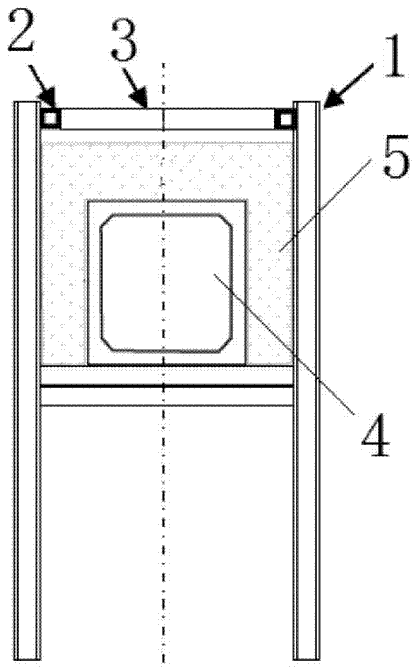
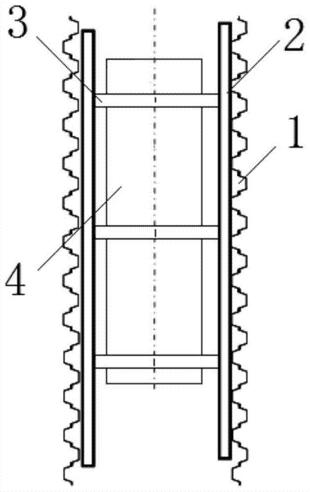
[0031] Such as figure 1 and 2 As shown, the foundation pit backfilling sand vibration compaction method includes the following steps: driving a pair of steel sheet piles 1 → supporting the pair of steel sheet piles through purlins 2 and support rods 3 → excavating the foundation pit → pipe gallery 4 structure The construction is placed in the foundation pit → waterproof the pipe gallery structure → backfill sand on both sides and the top of the pipe gallery 5 → pour water into the backfill sand in the foundation pit for preliminary compaction → remove the purlins and support rods → clamp the steel plate with a vibrating hammer Pile, pull out the steel sheet pile ...


PUM


Abstract

The invention discloses a vibration-compacting method for foundation pit backfill sand, which comprises the following steps: 1) driving steel sheet piles; 2) supporting a pair of steel sheet piles through purlins and support rods; 3) excavating the foundation pit; 4 ) The pipe gallery structure construction is placed in the foundation pit; 5) The sides and top of the pipe gallery are backfilled with sand; 6) The backfilled sand in the foundation pit is filled with water for preliminary compaction; 7) The purlins and support rods are removed; 8) Vibration hammer is used Clamp the steel sheet pile, pull out the steel sheet pile by vibration, and use the vibration force of the pile to compact the backfill sand; 9) Check the density of the backfill sand at one time; 10) Backfill the surface soil and complete the project. The use of mechanical compaction instead of manual compaction avoids manual work in poor environments and improves the working environment; one-time backfilling of sand reduces multiple conversions of processes, speeds up the construction progress, saves layered inspections, and reduces costs.

Description

technical field [0001] The invention relates to the technical field of building construction, in particular to a method for vibrating and compacting foundation pit backfill sand. Background technique [0002] The existing foundation pit backfilling sand compaction usually adopts the layered compaction method. The layered compaction method has the following disadvantages: 1. Since the distance between the comprehensive pipe gallery and the steel sheet pile foundation pit wall is only about 1 meter, the traditional manual hand jumping ramming method is used. , the working space is narrow, safety accidents such as bruises are prone to occur, the working environment is humid, and the quality of manual work is difficult to control; 2. The traditional manual compaction energy is small, the layers are flat and compact, and the layers are inspected. Only after passing the inspection can the upper layer be filled Sand has many process conversions and low efficiency; 3. Generally, the...

Claims


Application Information

Patent Timeline
Patent Type & Authority Patents(China)
IPC IPC(8): E02D17/02E02D17/04E02D17/18E02D9/02E02D3/046
Inventor 殷良君
Owner CCCC SHEC FOURTH ENG
Why Eureka
Try Eureka