Full-web type steel box transfer beam and connecting structure of full-web type steel box transfer beam and reinforced concrete shear wall

A technology for converting beams and concrete, applied in building structures, walls, building components, etc., can solve the problems of high connection cost, increased foundation load, and increased construction cost, and achieves improved pouring efficiency, reduced structural cost, and reduced foundation load. Effect

Inactive Publication Date: 2015-11-18
ARCHITECTURAL DESIGN RES INST OF GUANGDONG PROVINCE
View PDF7 Cites 3 Cited by
  • Summary
  • Abstract
  • Description
  • Claims
  • Application Information

AI Technical Summary

Problems solved by technology

[0005] First, in order to avoid the influence of too large and too many concrete pouring holes on the stiffness and shear bearing capacity of the transfer beam, in the prior art, the above-mentioned composite beam only needs to open 1 to 2 concrete pouring holes on the roof DINGBAN. Concrete is poured into the inner cavity NQ of the steel box girder GXL, which makes the concrete pouring process more troublesome, and it is easy to cause the problem that the inner cavity NQ of the steel box girder GXL is not completely filled by the concrete HNT;
[0006] Second, the steel box girder GXL components of the above-mentioned composite beams use a lot of steel and have a relatively large dead weight. Therefore, the above-mentioned composite beams are difficult to apply to the cantilever conversion and long-span conversion in high-rise buildings, and it will also increase the cost of the superstructure of the building , The load on the foundation increases, and the overall cost of the building increases;
[0007] Third, for the case where a reinforced concrete shear wall is installed above the transfer beam, the steel box girder GXL of the above-mentioned composite beam needs special structural treatment to ensure the reliability of the connection with the reinforced concrete shear wall, and the connection cost is relatively high. High, cumbersome construction

Method used


Image

  • Full-web type steel box transfer beam and connecting structure of full-web type steel box transfer beam and reinforced concrete shear wall
  • Full-web type steel box transfer beam and connecting structure of full-web type steel box transfer beam and reinforced concrete shear wall
  • Full-web type steel box transfer beam and connecting structure of full-web type steel box transfer beam and reinforced concrete shear wall

Examples


Embodiment 1

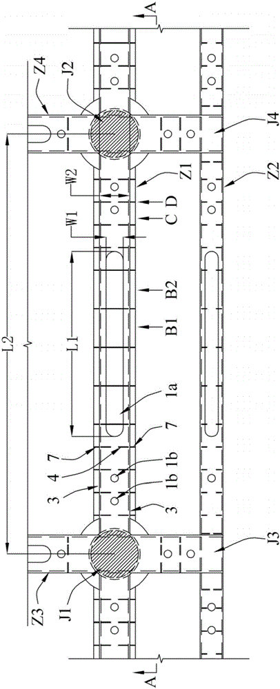
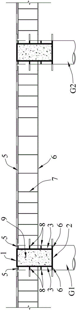
[0044] Such as Figure 2 to Figure 7 As shown, the solid-web steel box transfer girder according to Embodiment 1 of the present invention includes a steel box girder and concrete 9 . in, figure 2 shows the four solid-web steel box transfer beams Z1~Z4 applied in a transfer layer, the two adjacent supports J1 and J2 of the solid-web steel box transfer beam Z1, and the solid-web steel box transfer The two adjacent supports J3 and J4 of the beam Z2, among them, the support J1 is the beam-column joint between the solid-web steel box transfer beam Z1 and the structural column G1, and the support J2 is the solid-web steel box transfer beam Z1 and the structural Beam-column connection for column G2.

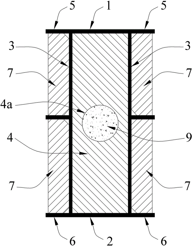
[0045] The above-mentioned steel box girder has a tubular main body connected by a top plate 1, a bottom plate 2, and two webs 3. The inner cavity a of the tubular main body is provided with a plurality of transverse partitions 4 distributed along the axial direction of the tubular m...

Embodiment 2

[0052] Such as Figure 8-1 to Figure 8-3 As shown, the solid-web steel box transfer girder of the second embodiment of the present invention is basically the same as the first embodiment, and their difference is that in the second embodiment, the inner cavity a of the tubular main body of the steel box girder is provided with a longitudinal partition 10, the longitudinal partition 10 extends along the axial direction of the tubular body and divides the inner cavity a of the tubular body into an upper chamber a1 and a lower chamber a2; the concrete flow hole 4a is located in the upper chamber a1, and the concrete 9 is filled In the upper chamber a1, there is no concrete filling in the lower chamber a2; the four concrete flow gaps 4b of the transverse partition 4 are respectively arranged at the four corners of the part of the transverse partition 4 located in the upper chamber a1. Through such setting, when the solid-web steel box transfer beam of the second embodiment is subje...

Embodiment 3

[0054] Such as Figure 9 to Figure 11As shown, the connection structure between the transfer beam and the reinforced concrete shear wall according to the third embodiment of the present invention includes the transfer beam and the reinforced concrete shear wall 11 arranged on the transfer beam. Wherein, the transfer beam in the third embodiment adopts the solid-web steel box transfer beam, and the solid-web steel box transfer beam in the third embodiment is basically the same as the above-mentioned embodiment 1 or embodiment 2, except that: The solid-web steel box transfer beam in the third embodiment is provided with two steel plates 13 for connecting the reinforced concrete shear wall 11 on the upper end surface of the top plate 1 outside the concrete pouring opening 1a, and the two steel plates 13 are both Extends axially along the tubular body. Among the two rows of steel bars of the reinforced concrete shear wall 11 in the third embodiment, the lower ends of the steel ba...


PUM


Abstract

The invention discloses a full-web type steel box transfer beam and a connecting structure of the full-web type steel box transfer beam and a reinforced concrete shear wall. The full-web type steel box transfer beam comprises a steel box beam and concrete, wherein the steel box beam is provided with a pipe-shaped main body formed by connecting a top plate, a bottom plate and two web plates; each span, corresponding to the transfer beam, of the top plate is provided with a group of local open openings; each concrete casting opening in each group of local open openings is formed in the middle position of the span corresponding to the transfer beam; and each group of local open openings is provided with at least one exhaust hole in two hogging moment region ranges of the span corresponding to the transfer beam. The transfer beam has the advantages that on the premise that the normal cross-section bending-resistant performance, the torsion-resistant performance, the vertical shearing-resistant performance and the local stability are not lowered through being compared with those of a closed steel box-concrete composite beam without local open openings in the prior art, great convenience is brought for the concrete casting in the construction process; the concrete casting efficiency is improved; and the transfer beam is applicable to cantilever transfer and large-span transfer.

Description

technical field [0001] The invention relates to a solid-web steel box transfer beam and a connection structure between the transfer beam and a reinforced concrete shear wall. Background technique [0002] With the development of the national economy, the construction industry has put forward higher and higher requirements for building structures, which has promoted the continuous development of building structures in the direction of large-span, light weight, environmental protection, and multi-function. Traditional structures can no longer meet the requirements of modern building structures. Requirements, steel-concrete composite structures have been widely used in bridges, industrial plants, high-rise buildings, urban overpasses and other projects due to their high bearing capacity, light weight, small structure size, good seismic performance, and convenient construction. One of the important development directions of the structure. [0003] figure 1 It shows a closed st...

Claims


Application Information

Patent Timeline
Patent Type & Authority Applications(China)
IPC IPC(8): E04B5/23E04B5/28E04B2/56E04B2/64
Inventor 罗赤宇邓汉荣蒋运林程博张啸辰徐裕坚吴金保许振刚叶国认林景华张守林张梦青苏龙云陈积奋黎国彬
Owner ARCHITECTURAL DESIGN RES INST OF GUANGDONG PROVINCE
Why Eureka
Try Eureka