Eureka AIR delivers breakthrough ideas for toughest innovation challenges, trusted by R&D personnel around the world.

Method for solving moving cam profile in uniform acceleration transitional motion of roller follower

A technology of roller push rod and constant acceleration, applied in transmission parts, belt/chain/gear, mechanical equipment, etc., can solve the problems of lack of reference method and unreasonable design for cam profile solution

Active Publication Date: 2015-11-18
CHANGZHOU UNIV
View PDF7 Cites 1 Cited by
  • Summary
  • Abstract
  • Description
  • Claims
  • Application Information

AI Technical Summary

Problems solved by technology

[0005] In order to overcome the deficiencies in the prior art, the present invention provides an intuitive and easy-to-grasp method for solving the contour of the moving cam when the roller push rod is in constant-acceleration reciprocating direct motion, so as to solve the problems in the current design of this type of moving cam mechanism. Problems such as the lack of reference methods or the difficulties and unreasonable design caused by the solution of the cam profile

Method used


Image

  • Method for solving moving cam profile in uniform acceleration transitional motion of roller follower
  • Method for solving moving cam profile in uniform acceleration transitional motion of roller follower
  • Method for solving moving cam profile in uniform acceleration transitional motion of roller follower

Examples


Embodiment Construction

[0030] The implementation process of the method for solving the moving cam profile of the present invention will be described in detail below in conjunction with the accompanying drawings.

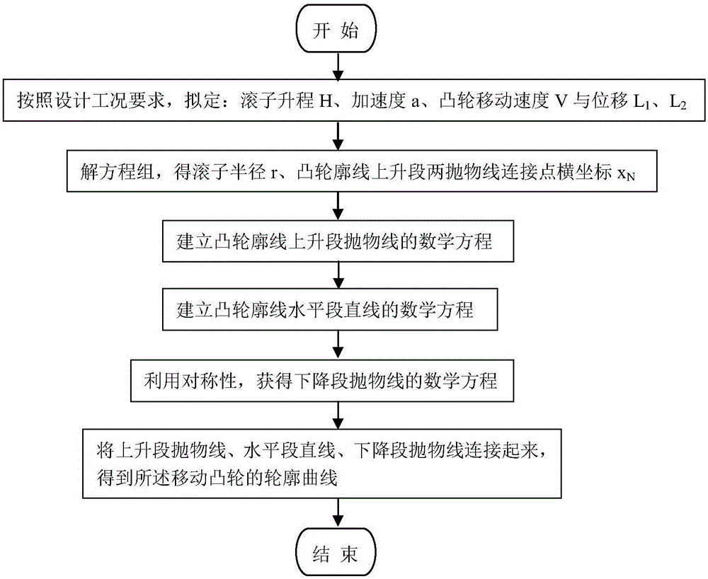
[0031] 1) Start the system;

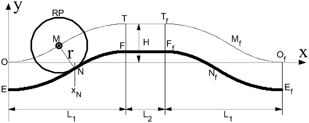
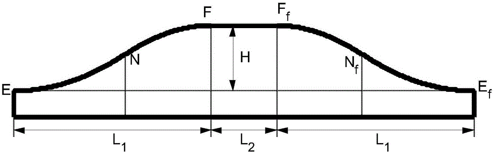
[0032] 2) According to the design conditions or the actual requirements of the production site, formulate the lift H of the roller push rod, the acceleration a when the roller push rod is in direct motion with constant acceleration, the moving speed V of the cam, and the lift of the roller push rod Cam displacement L corresponding to H 1 , and the horizontal segment straight line FF f Corresponding cam displacement L 2 ;

[0033] 3) Taking into account the smooth and continuous contour of the moving cam without cusp or distortion, and considering the requirement that the movement speed of the roller push rod does not change suddenly, solve equations (1) and (2) simultaneously to obtain the roller push rod The roller radius r of the rod, the abscissa x of t...


PUM


Abstract

The invention provides a method for solving a moving cam profile in uniform acceleration transitional motion of a roller follower. The method aims to overcome the defects that in existing design of a moving cam mechanism, reference methods lack in solving of a cam profile curve, and the moving cam mechanism is designed by experience. The cam profile obtained through the solving method comprises ascending section parabolas EN and NF, a horizontal section straight line FFf and descending section parabolas FfNf and NfEf, and all the sections are connected to obtain a profile curve of a moving cam. The method has the beneficial effects that according to the moving cam profile solved through the method, when the roller follower performs uniform acceleration reciprocating linear movement, the moving speed of the follower does not suddenly change, rigid impact of the cam mechanism is eliminated, vibration and noise of transmission pieces are lowered, and therefore the service life of the cam mechanism is prolonged; the method for solving the moving cam profile is simple, visual and easy to master; the solved cam profile is smooth and continuous, and the cuspidal point or distortion phenomenon is avoided, so that machining through a numerical control machine tool is facilitated, and the production efficiency is high.

Description

technical field [0001] The invention relates to a method for solving the contour of a cam, in particular to a method for solving the contour of a moving cam when a roller push rod performs constant-acceleration direct motion, and belongs to the technical field of cam mechanism design. Background technique [0002] The cam is a component with a curved profile that can control the movement of the follower, and the mechanism containing the cam is called a cam mechanism. The cam mechanism is simple and compact in structure, takes up little space, and works reliably. For almost any required movement law of the follower, the cam profile can be designed to realize it. Therefore, the cam mechanism has become a common mechanism in various machines, especially in automatic machinery and automatic control devices, especially in high-speed, high-precision transmission and indexing mechanisms and guiding mechanisms. It has irreplaceable advantages. The profile of the cam and the followe...

Claims


Application Information

Patent Timeline
Patent Type & Authority Applications(China)
IPC IPC(8): F16H53/00
CPCF16H53/00F16H2057/0087
Inventor 祝海林邹旻
Owner CHANGZHOU UNIV
Why Eureka
Eureka Blog
Learn More