
Cooling and heating dual-purpose indoor temperature regulating system driven by wind power

A technology for dual-use heating and cooling, and an adjustment system, applied in air conditioning systems, wind turbines, wind turbine combinations, etc., can solve problems such as difficulty in effectively cooling high-temperature air, no radiator at the outlet of the air compressor, and poor cooling effect. Simple and reliable, takes up less space, and increases the effect of reliability

Active Publication Date: 2015-11-18
ZHEJIANG UNIV
View PDF7 Cites 6 Cited by
  • Summary
  • Abstract
  • Description
  • Claims
  • Application Information

AI Technical Summary

Problems solved by technology

But this technical solution has the following disadvantages: 1. There is no radiator at the outlet of the air compressor, so it is difficult to effectively cool the high-temperature air generated by compression, and the cooling effect is poor
2. Use the heat exchanger to supply cooling or heating to the room. Since both sides of the heat exchange wall are air, the heat transfer coefficient is low.
3. Since there is no reversing valve, two independent heat exchangers are required for indoor cooling and heating, which increases the cost
However, this patented technology is only suitable for the vehicle-mounted environment and requires the power of the vehicle to drive the air compressor. In addition, it also has the following disadvantages: 1. There is no radiator at the outlet of the air compressor, and the cooling effect is poor.
2. The heat exchanger is used to cool or heat the room, and the heat transfer coefficient is low

Method used

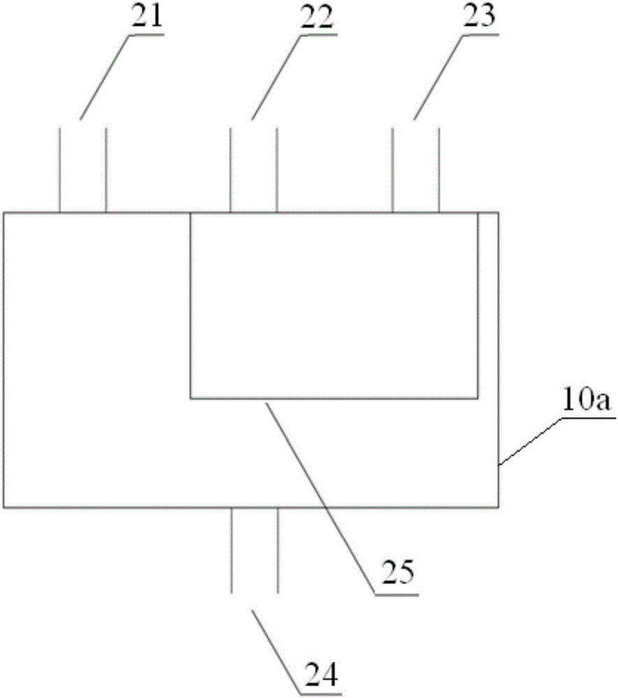
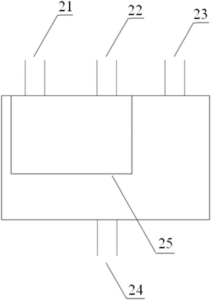

Image

  • Cooling and heating dual-purpose indoor temperature regulating system driven by wind power
  • Cooling and heating dual-purpose indoor temperature regulating system driven by wind power
  • Cooling and heating dual-purpose indoor temperature regulating system driven by wind power

Examples


Embodiment Construction

[0034] The present invention will be described in further detail below in conjunction with the accompanying drawings.

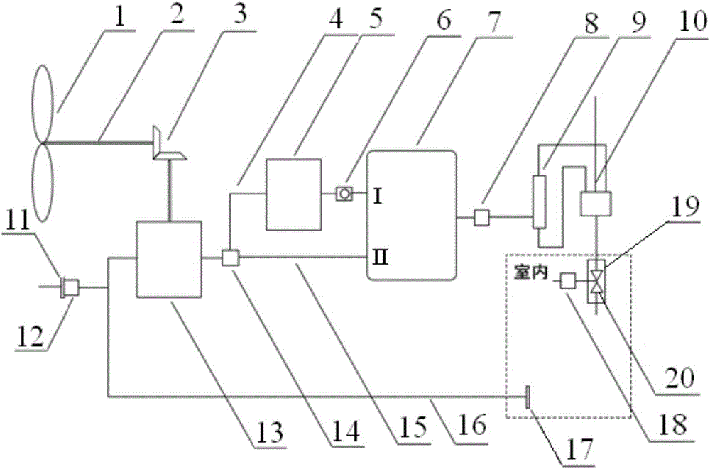
[0035] like figure 1As shown, a wind-driven dual-purpose room temperature adjustment system includes a power device, an air supply device and a return air device; wherein the power device includes a wind turbine 1, an air compressor 13, a three-way valve 14, a transmission shaft 2 and gears Group 3; the air supply device includes a radiator 5, a one-way valve 6, a gas storage tank 7, a first gate valve 8, a vortex tube 9, a first gas delivery pipe 4, a second gas delivery pipe 15, a reversing valve 10 and a second gate valve 18. Muffler 19 and mixer 20; the air return device includes a first filter 17, a return air pipe 16, a third gate valve 12 and a second filter 11.

[0036] The connection relationship of the above components is as follows:

[0037] The output end of the wind turbine 1 is connected to the transmission shaft 2 for transmission, and the ou...


PUM


Abstract

The invention discloses a cooling and heating dual-purpose indoor temperature regulating system driven by wind power. The system comprises an air compressor, a wind turbine providing power for the air compressor, and a vortex tube communicated with an outlet of the air compressor, wherein the vortex tube is connected with the tail end of an indoor air conditioner through a reversing valve, and the reversing valve can make a cold end outlet of the vortex tube communicated with the tail end of the indoor air conditioner to be in the refrigerating mode and make a hot end outlet of the vortex tube communicated with the tail end of the indoor air conditioner to be in the heating mode. According to the system, the refrigerating mode and the heating mode are realized, air is utilized as the working medium, the structure is simple and reliable, cost is low, electric energy is not needed at all, and the system can serve as an indoor temperature adjusting device in remote regions lacking electric power or as supplement energy-saving devices of air conditioners in ordinary families.

Description

technical field [0001] The invention belongs to the technical field of air-conditioning design, in particular to a wind-driven cooling and heating dual-purpose room temperature adjustment system. Background technique [0002] Existing air-conditioning systems are generally driven by electricity. Since most of my country's electricity is provided by thermal power plants, its overall energy utilization efficiency is low. A device that directly utilizes natural energy and realizes cooling or heating through mechanical transmission can achieve high energy conversion efficiency. The existing wind-powered refrigeration and heating devices use refrigerant as the working medium, and are closed systems with two heat exchangers, which have the disadvantages of complex devices, high investment costs, inability to realize energy storage, and poor reliability. Existing wind heating devices generally generate heat by stirring oil or injecting oil, which has the disadvantages of bulky, lo...

Claims


Application Information

Patent Timeline
Patent Type & Authority Applications(China)
IPC IPC(8): F25B9/00F24F5/00F03D9/00
CPCY02E10/72F25B9/00F03D9/00F24F5/0046
Inventor 曾昭赟王勤田在鑫赵晨曦王世宽
Owner ZHEJIANG UNIV
Learn More