A circulating fluidized bed air drying system

A circulating fluidized bed, fluidized bed technology, applied in chemical instruments and methods, dehydration/drying/thickened sludge treatment, energy wastewater treatment, etc., can solve the problems of large weather influence, low efficiency, limited application area, etc. It achieves the effects of high degree of automation, less equipment occupation and high drying efficiency

Active Publication Date: 2015-11-18
嘉兴绿方舟环保技术有限公司
View PDF11 Cites 0 Cited by
  • Summary
  • Abstract
  • Description
  • Claims
  • Application Information

AI Technical Summary

Problems solved by technology

Mechanical drying usually needs to add chemicals to the sludge. The chemicals will increase the amount of sludge and have an adverse effect on the subsequent treatment. What's more unfavorable is that mechanical drying usually cannot reduce the water content in the case of using chemicals. to less than 50%
Solar drying occupies a large area, has low efficiency, is greatly affected by the weather, and has limited applicable areas

Method used


Image

  • A circulating fluidized bed air drying system
  • A circulating fluidized bed air drying system
  • A circulating fluidized bed air drying system

Examples


Embodiment 1

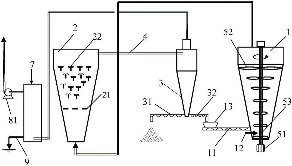
[0020] In the working process of a circulating fluidized bed air-drying system of the present invention, the fluidized bed air-drying tower 2 adopts the induced draft fan 81 connected to the upper end of the deodorizing device 7 to continuously draw air to form a negative pressure condition, and can work as usual in rainy weather. 32 By adjusting the circulation ratio to adapt to the granulation, fluidization and air-drying of materials with different moisture content and properties, the rotary crusher 1 adopts power rotary air-drying, on the one hand, it can ensure the wind speed, so that the material particles can fully contact with the air for mass transfer, on the other hand It can continuously break the particles, and those large-size particles will continue to settle down along the outer wall of the cone, and finally be crushed again by the crusher at the bottom, and then take off with the wind and join the rotating fluidized bed. The wind-driven rotary filler 22 can use ...

Embodiment 2

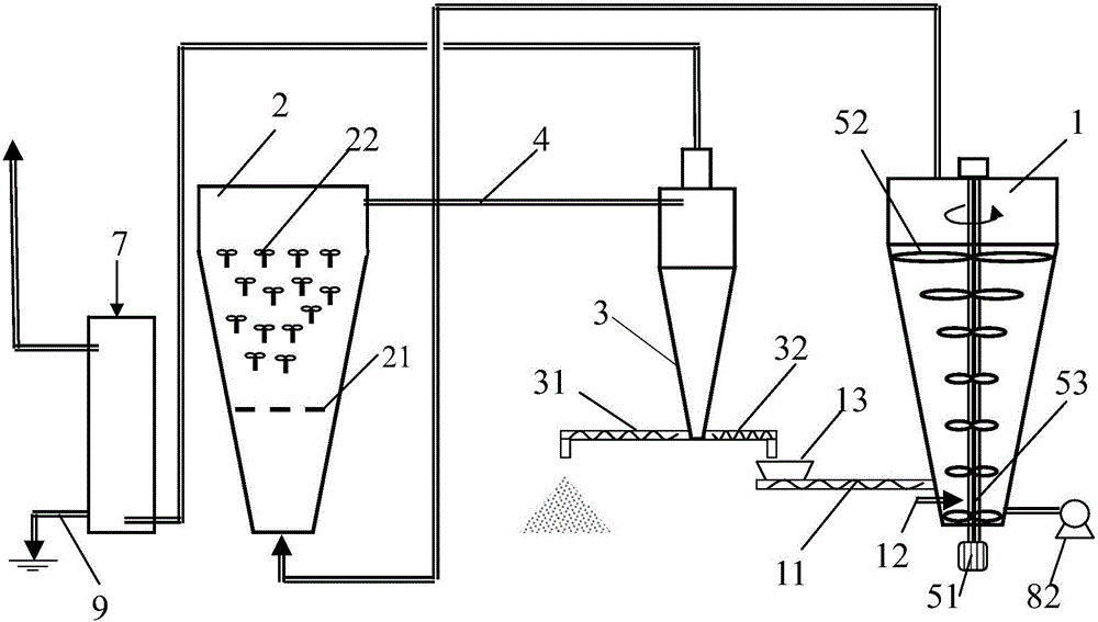
[0022] During the working process of a circulating fluidized bed air-drying system of the present invention, the fluidized bed air-drying tower 2 continuously blows air through the blower 82 connected to the bottom of the rotary breaker 1, and can work as usual in rainy weather. The circulating conveyor 32 adjusts the circulation ratio To adapt to the granulation, fluidization and air-drying of materials with different moisture content and properties, the rotary crusher 1 adopts power rotary air-drying. On the one hand, it can ensure the wind speed, so that the material particles can fully contact with the air for mass transfer, and on the other hand, it can continuously crush the particles. , Those large-sized particles continuously settle down along the outer wall of the cone, and finally are crushed again by the crusher at the bottom, and then take off with the wind and join the rotating fluidized bed. The wind-driven rotary filler 22 can use the wind speed to form a high-sp...


PUM


Abstract

The invention discloses a circulating fluid bed air-drying system which comprises a rotary crusher, a fluidized bed air-drying tower and a gas-solid separator, wherein a crusher is installed in the rotary crusher; the lower end of the rotary crusher is provided with a feed conveyor; the rotary crusher is connected with the fluidized bed air-drying tower through a pipeline; a plurality of wind rotary fillers are arranged in the fluidized bed air-drying tower; the fluidized bed air-drying tower is connected with the gas-solid separator through a pipeline; one side of the bottom of the gas-solid separator is provided with a discharge conveyor; the other side of the bottom of the gas-solid separator is provided with a circulating conveyor; the feed conveyor is positioned below the circulating conveyor; and the outlet material from the circulating conveyor enters the feed conveyor and is mixed with the inlet material. Multiple crushing mechanisms are arranged to implement overall full-range crushing from bottom to air and from power-on to power-off, so that new surfaces of the granules are continuously exposed in the air-drying process, and the granules are replaced with high-velocity air flow to take moisture away; and thus, the air-drying efficiency is high.

Description

【Technical field】 [0001] The invention relates to the technical field of a sludge air-drying system, in particular to the technical field of a power cyclone fluidized bed circulating air-drying system for urban sludge. 【Background technique】 [0002] With the acceleration of industrialization and urbanization, the volume of sewage treatment in my country is increasing, and the corresponding sludge production is increasing rapidly. The annual sewage treatment volume of the "Twelfth Five-Year Plan" will reach 50 billion cubic meters, and the corresponding annual sludge (80% moisture content) production will be about 40 million tons; by 2020, my country's sludge production is expected to exceed 60 million tons per year . So far, most of the sludge has not been properly treated, and the problem of secondary pollution is prominent. [0003] The common technical routes for sludge treatment and disposal in my country include landfill, composting, and incineration. Sludge usually n...

Claims


Application Information

Patent Timeline
Patent Type & Authority Patents(China)
IPC IPC(8): C02F11/00C02F11/12
CPCY02W10/37
Inventor 朱忆人
Owner 嘉兴绿方舟环保技术有限公司
Why Eureka
Try Eureka