High-efficiency melting furnace of phase-changing heat storage medium

A phase-change heat storage and melting furnace technology, which is applied to furnaces, crucible furnaces, furnace types, etc., can solve the problems of large heat loss, increase the overall weight of equipment, and cannot be repaired, so as to reduce the heat resistance requirements of equipment and save equipment The effect of investing money and avoiding heat loss

Inactive Publication Date: 2015-11-18
殷苏
View PDF9 Cites 2 Cited by
  • Summary
  • Abstract
  • Description
  • Claims
  • Application Information

AI Technical Summary

Problems solved by technology

Because the heat is absorbed in the tube, it is easy to cause uneven local heat absorption, resulting in the decomposition of the phase-change heat storage medium due to the high temperature, forming an adsorption film, which is adsorbed on the inner wall of the heat-absorbing tube, which will reduce the heat-absorbing efficiency over time and affect the safe operation of the system; At the same time, because the phase change heat storage medium absorbs heat in the tube, the equipment is prone to blockage during operation, causing irreparable damage and affecting the safety of the entire phase change heat storage medium melting system
There are many types of system equipment, poor compatibility, and high investment costs
[0005] When the round crucible phase-change medium melting furnace is working, the solid phase-change medium can directly enter the melting device, but there is a combustion chamber outside the inner pot for the combustion equipment to work, and the other side of the combustion chamber is wrapped with heat-insulating refractory

Method used


Image

  • High-efficiency melting furnace of phase-changing heat storage medium
  • High-efficiency melting furnace of phase-changing heat storage medium
  • High-efficiency melting furnace of phase-changing heat storage medium

Examples


Example Embodiment

[0051] Example 1

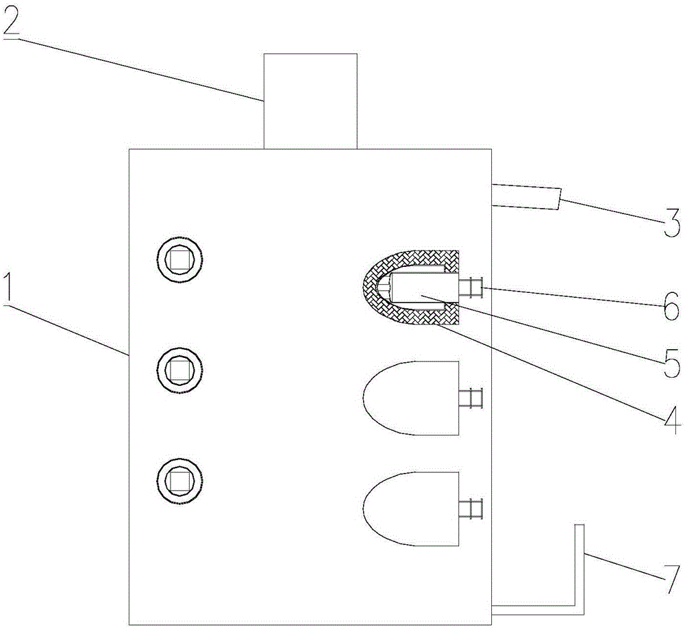
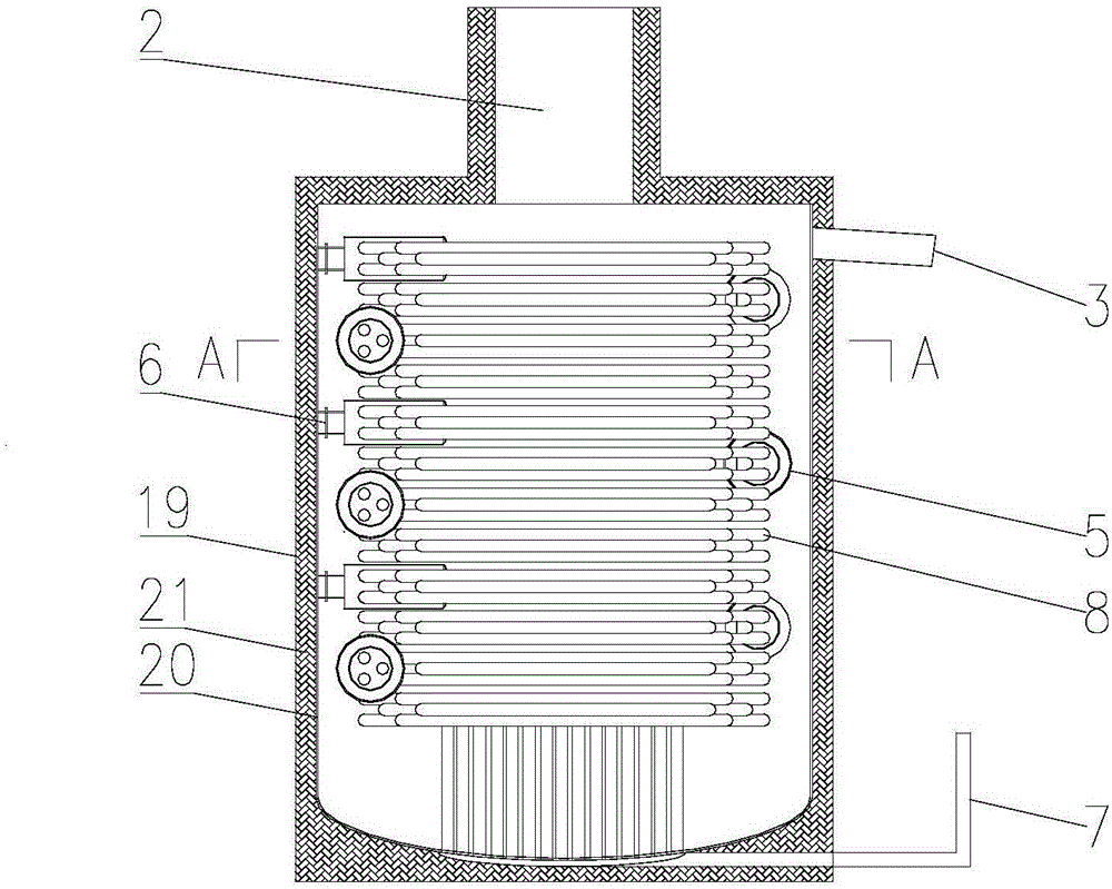
[0052] like Figure 1-Figure 3 As shown, a high-efficiency phase-change heat storage medium melting furnace includes:

[0053] Insulation cylinder 1, insulation cylinder 1 has a filling port 2 for filling phase change heat storage medium, and a discharge port 3 for discharging liquid phase change heat storage medium, and the outer wall of insulation cylinder 1 is provided with several The support pipe 4 that connects the inside and outside of the heat preservation cylinder 1, several support pipes 4 are evenly arranged on the outer wall of the heat preservation cylinder 1, a heating chamber 5 is fixed in the support pipe 4, and the heating chamber 5 is sealed and connected with the support pipe 4. The inside of the insulation cylinder 1 is isolated from the outside,

[0054] Heating burner 6, and heating burner 6 is fixedly arranged in heating chamber 5, and

[0055] The smoke exhaust pipe 7 , each heating chamber 5 and the smoke exhaust pipe 7 communicat...

Example Embodiment

[0066] Example 2

[0067] like Figure 4 , Figure 5 As shown, a high-efficiency phase-change heat storage medium melting furnace has the same structure as that of Embodiment 1, the difference is that: the filling port 2 is provided with a sealed filling box 9 that prevents the hot gas in the melting furnace from overflowing, and the sealing Filling box 9 comprises box body 10, and box body 10 is provided with rotating shaft 11, and rotating shaft 11 is fixed with some sealing baffles 12 upwards, and the rotation of rotating shaft 11 is driven by drive motor 13 outside box body 10.

[0068] Preferably, several sealing baffles 12 are evenly arranged in the circumferential direction of the rotating shaft 11 .

Example Embodiment

[0069] Example 3

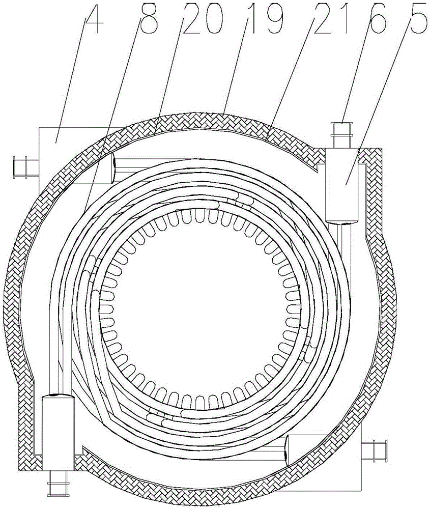
[0070] like Image 6 , Figure 7 As shown, a high-efficiency phase-change heat storage medium melting furnace has the same structure as that of embodiment 1 or embodiment 2. The discharge port 3 is arranged on the upper part of the side wall of the melting furnace, and a discharge port 3 inside the insulation cylinder 1 is fixedly provided with a The baffle 14 used to prevent the solid phase-change heat storage medium added from the filling port 2 from entering the discharge port 3 .

[0071] Preferably, the baffle plate 14 , the inner wall of the insulation cylinder 1 and the top of the insulation cylinder 1 form a liquid phase-change heat storage medium discharge channel 15 with an opening at the bottom.

[0072] Preferably, the discharge channel 15 is provided with a vent 16 for releasing the air in the discharge channel 15 .

[0073] Preferably, the vent 16 is located at the top of the insulation cylinder 1 or at the side wall of the insulation cylind...


PUM


Abstract

The invention relates to the technical field of heat storage devices, in particular to a high-efficiency melting furnace of a phase-changing heat storage medium. The high-efficiency melting furnace comprises a heat preserving cylinder body, heating burners and a smoke discharging pipe, wherein the heat preserving cylinder body is provided with an injection port for injecting the phase-changing heat storage medium, and a discharge port for discharging a liquid phase-changing heat storage medium; a plurality of supporting pipes for enabling the inside of the heat preserving cylinder body to be communicated with the outside of the heat preserving cylinder body are arranged on the outer side wall of the heat preserving cylinder body; a heating cavity is fixed in each supporting pipe, and connected with the corresponding supporting pipe in a sealed manner; the inside of the heat preserving cylinder body is isolated from the outside of the heat preserving cylinder body; the heating burners are fixedly arranged in the heating cavities; the heating cavities are connected with the smoke discharging pipe through a plurality of heating pipes respectively arranged at the inner part of the heat preserving cylinder body. According to the high-efficiency melting furnace of the phase-changing heat storage medium, disclosed by the invention, the heat generated by the heating burners directly enters the heat preserving cylinder body through the heating pipes to be exchanged, so that the solid phase-changing heat storage medium is molten into liquid; the high-efficiency melting furnace is high in salt melting efficiency and heat utilization ratio.

Description

technical field [0001] The invention relates to the technical field of energy storage devices, in particular to a high-efficiency phase-change heat storage medium melting furnace. Background technique [0002] Energy storage is a key and essential link in a solar thermal power generation system. The energy storage medium is mostly a phase-change heat storage medium, which absorbs and releases heat through the phase change of the heat storage medium, thereby realizing the heat storage function. In a commercially operated photothermal power station, the amount of phase change heat storage medium used is generally about 30,000 tons or more, and the melting capacity of the melting furnace is generally more than 720 tons per day. The melting speed is fast, efficient and safe. The furnace has become a must for the construction of solar thermal power plants. [0003] There are two kinds of phase change medium melting furnaces currently in use, one is the traditional shell and tube...

Claims


Application Information

Patent Timeline
IPC IPC(8): F27B14/14
Inventor 张雷殷辉
Owner 殷苏
Why Eureka
Try Eureka