
Gas-liquid heat exchanger heat transfer coefficient measuring device

A measuring device and technology of heat transfer coefficient, applied in the direction of thermal conductivity of materials, etc., can solve problems such as inability to measure, measurement of heat transfer coefficient of gas-liquid heat exchangers, and gas-liquid heat exchangers without heat transfer coefficients, etc. achieve the effect of increasing power consumption

Inactive Publication Date: 2018-06-12
ZHEJIANG UNIV
View PDF11 Cites 0 Cited by
  • Summary
  • Abstract
  • Description
  • Claims
  • Application Information

AI Technical Summary

Problems solved by technology

As pointed out above, the heat transfer coefficient measuring device of the heat exchanger has a strong pertinence to the structure of the heat exchanger. The application number 86102931 is only suitable for the measurement of the heat transfer coefficient of the slab; the application number 201010587371.6 is suitable for the heat transfer of the light tube Coefficient measurement, because it is measured by water as the medium, is not suitable for the measurement of gaseous medium; the application number is 200510088762.2 is also only applicable to the determination of the heat transfer coefficient of liquid medium; although the application number is 200410074334.X does not limit the heat transfer medium, However, it is not applicable to the determination of the heat transfer coefficient of the gas-liquid heat exchanger with fin extension, because it cannot measure the important index of gas phase pressure drop, which is very important for power consumption and meeting the requirements of subsequent processes
Therefore, although there are multiple heat transfer coefficient test and evaluation devices at present, there is no heat transfer coefficient measurement and evaluation device that can be used for comprehensive testing and evaluation of gas-liquid heat exchangers.

Method used


Image

  • Gas-liquid heat exchanger heat transfer coefficient measuring device
  • Gas-liquid heat exchanger heat transfer coefficient measuring device
  • Gas-liquid heat exchanger heat transfer coefficient measuring device

Examples


Embodiment Construction

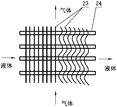
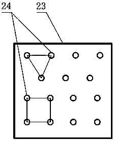
[0019] The present invention will be further described below in conjunction with the accompanying drawings and embodiments.

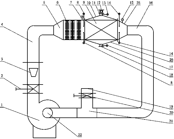
[0020] Such as figure 1 , figure 2 , image 3 As shown, the air outlet of the blower fan 1 of the present invention is equipped with a regulating valve 2, and a flowmeter 3 is installed in the pipeline of the outlet of the regulating valve 2, and one end of the pipe 4 with a 90° elbow is connected with the outlet end of the flowmeter 3, and the other end Connect to the small end of the first different diameter channel 5; the inlet end of the gas heater 6 is connected to the large end of the first different diameter channel 5, and the outlet end of the gas heater 6 is connected to the inlet end of the gas-liquid heat exchanger 9 , the outlet end of the gas-liquid heat exchanger is connected to the large end of the second different-diameter channel 25, and the small end of the second different-diameter channel 25 is connected to the first end of the te...


PUM


Abstract

The invention discloses a gas-liquid heat exchanger heat transfer coefficient determination apparatus. The apparatus comprises a blower fan, a regulating valve, a gas flowmeter, two reducing crosses, a gas heater, a gas-liquid heat exchanger, tee or the like which are connected by pipelines, thereby forming a channel for gas phase fluid. A liquid inlet end of the gas-liquid heat exchanger is connected with a small end of one of the two reducing crosses, the big end of the reducing cross is connected with the gas-liquid heat exchanger, the small end of the reducing cross is connected with a fluid flowmeter; a liquid outlet end of the gas-liquid heat exchanger is equipped with the other reducing cross, and the big end of the reducing cross is connected with the gas-liquid heat exchanger, thereby forming a channel of liquid phase fluid. A gas inlet and a gas outlet of the heat exchanger are provided with temperature sensors and pressure sensors, and the liquid inlet and the liquid outlet of the heat exchanger are provided with temperature sensors. The apparatus provided by the invention is used for heat transfer coefficient test of the gas-liquid heat exchanger, thereby obtaining data needed for high efficiency heat transfer. Gas side fluid circulation and utilization is used, and a small amount of supplied gas is used for adjusting by a vent nozzle adjusting valve, thereby reducing energy loss during the experiment process.

Description

technical field [0001] The invention relates to a test device for the heat transfer coefficient of a heat exchanger, in particular to a device for measuring the heat transfer coefficient of a gas-liquid heat exchanger. Background technique [0002] Due to different heat exchange objects, different use occasions, and different heat transfer media, there are many types of heat exchangers. From the different physical states of the media, they are mainly divided into gas-gas heat exchange and gas-liquid heat exchange. , Liquid-liquid heat exchange, there are some heat exchanges involving phase change in the middle, for heat exchangers with different properties and different phase media, their structural forms are different, such as the thermal conductivity of the liquid phase is very high, but the gaseous phase The thermal conductivity of the phase is very low, so the thermal resistance is mainly concentrated on the gaseous side. In order to improve the heat transfer coefficient...

Claims


Application Information

Patent Timeline
Patent Type & Authority Patents(China)
IPC IPC(8): G01N25/18
Inventor 郑传祥魏双何建龙冯苗根
Owner ZHEJIANG UNIV
Learn More