
Tunnel junction cantilever beam content testing instrument

A cantilever beam, tunnel junction technology, applied in instruments, measuring devices, scientific instruments, etc., can solve problems such as high price, complex structure of instruments and equipment, and limitations of use occasions or application fields.

Inactive Publication Date: 2015-11-18
YANGZHOU UNIV
View PDF4 Cites 0 Cited by
  • Summary
  • Abstract
  • Description
  • Claims
  • Application Information

AI Technical Summary

Problems solved by technology

[0004] Although the method of using tunneling current to detect distance or displacement has a high resolution, the current equipment (including scanning tunneling microscopes) using this method is complex in structure, requires special personnel to operate, and needs to be calibrated many times during use. Expensive, very limited in use occasions or application fields

Method used


Image

  • Tunnel junction cantilever beam content testing instrument
  • Tunnel junction cantilever beam content testing instrument
  • Tunnel junction cantilever beam content testing instrument

Examples


Embodiment Construction

[0021] The specific implementation of a tunnel junction cantilever beam content measuring instrument of the present invention will be described below with reference to the accompanying drawings.

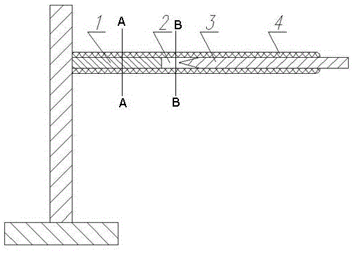
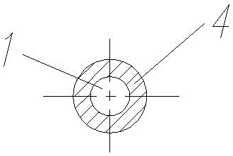
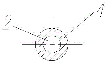
[0022] Such as figure 1 , figure 2 , image 3 As shown, there is a hole in the middle of a cantilever beam made of fiber, and metal electrode 1 and metal electrode 3 are arranged in the hole, and insulating fiber 4 wraps metal electrode 1 and metal electrode 3, leaving a distance between metal electrode 1 and electrode 3 2. The part of the metal electrode 3 close to the metal electrode 1 is in the shape of a needle point. The tester is a cantilever beam structure, and one or more pairs of tunnel junction electrodes are installed near the fixed end of the cantilever beam. The distance between two adjacent electrodes is 0.01nm-100nm, and the electrodes are insulated from the cantilever beam. The shape of the cantilever beam is uniform cross section or uneven cross section, the unif...


PUM

PropertyMeasurementUnit
sizeaaaaaaaaaa
sizeaaaaaaaaaa

Abstract

The invention discloses a tunnel junction cantilever beam content testing instrument. The testing instrument is of a cantilever beam structure, one or more pairs of tunnel junction electrodes are installed on the part close to the fixed end of a cantilever beam, the tunnel junction electrodes are oppositely arranged in the length direction of the cantilever beam, the distance between every two adjacent electrodes ranges from 0.001 nanometer to 100 manometers, and the electrodes and the cantilever beam are insulated. The electrodes are in a stick shape or a strip shape or a thin film shape, the part, close to another metal electrode, of one metal electrode is a needle-tip-shaped or needle-tip-like-shaped polyhedron with the dimension ranging from 0.01 nanometer to 100 manometers, and the part, opposite to the corresponding polyhedron, of another metal electrode is a needle-tip-shaped or flat surface ranging from 0.01 nanometer to 100 manometers. The electrodes are made of platinum or tungsten or iridium or a mixture of platinum, tungsten and iridium. The content of matter can be measured by measuring the numerical value of tunneling currents.

Description

technical field [0001] The invention relates to a tester for measuring substance content by monitoring the change of tunnel current. Background technique [0002] Since 1982, Dr. Gerd Binnig and Dr. Heinricn Rohrer of the Zurich Laboratory of International Business Machines Corporation have developed the world's first scanning tunneling microscope (STM) by using the tunneling effect in quantum mechanics, enabling humans to observe the movement of individual atoms on the surface of matter in real time for the first time. The arrangement state and the physical and chemical properties related to the surface electronic behavior not only provide a powerful observation and experimental tool for the development of nanotechnology, but also directly promote the rapid development of nanotechnology. As a milestone invention in the history of nanotechnology development, The scanning tunneling microscope is recognized by the international scientific community as one of the world's top te...

Claims


Application Information

Patent Timeline
Patent Type & Authority Applications(China)
IPC IPC(8): G01N27/60
Inventor 边义祥黄慧宇
Owner YANGZHOU UNIV
Learn More