Eureka AIR delivers breakthrough ideas for toughest innovation challenges, trusted by R&D personnel around the world.

Frequency converter power electronics controllable loading method based on grid connected inverter

A technology of power electronics and inverters, which is applied in the direction of instruments, measuring electricity, and measuring electrical variables, etc., can solve the problems of limited power consumption, energy waste, and waste of electric energy during the test process, and achieve controllable load characteristics and test system Simplicity, cost reduction effect

Active Publication Date: 2015-11-18
STATE GRID CORP OF CHINA +1
View PDF8 Cites 6 Cited by
  • Summary
  • Abstract
  • Description
  • Claims
  • Application Information

AI Technical Summary

Problems solved by technology

Hysteresis dynamometers, excitation motors and other simulated loads can be used for inverter testing, but energy-consuming loads not only completely waste the electrical energy in the test process, but also are affected by the control response speed and quality, making it difficult to accurately simulate the auxiliary loads of the inverter. machine load characteristics
On the other hand, energy-consuming loads are limited by heat dissipation and other factors, and the power consumption level is limited, which is limited to the simple test application of low-power inverters, and cannot be applied to the test of high-power inverters, and the remaining electric energy cannot be fed back to the inverter during the test. power grid, resulting in a waste of energy
At the same time, this test method is difficult to simulate the exact characteristics of the auxiliary load of the frequency converter

Method used


Image

  • Frequency converter power electronics controllable loading method based on grid connected inverter
  • Frequency converter power electronics controllable loading method based on grid connected inverter
  • Frequency converter power electronics controllable loading method based on grid connected inverter

Examples


Embodiment Construction

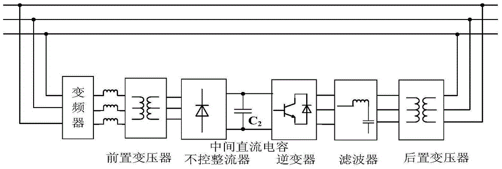
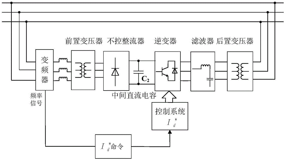
[0021] see figure 1 , the present invention provides a frequency converter power electronic controllable load method based on grid-connected inverter, the main circuit structure is divided into pre-transformer, uncontrolled rectifier, intermediate DC capacitor, inverter, filter And post transformer six parts. Two of the transformers have an isolation function, and the frequency converter, inverter, and power grid are all isolated, which improves the safety of the system and simplifies the design.

[0022] General inverter output line voltage effective value U sm =380V, when no pre-transformer is connected or when the transformation ratio of the pre-transformer is 1, after uncontrolled rectification, the DC capacitance C 2 The rated voltage is U dm ≈513V, which is obviously less than the input threshold voltage U that makes the inverter output 380V line voltage dT . There are two solutions for this: one is to step up the front transformer to increase the output voltage of ...


PUM


Abstract

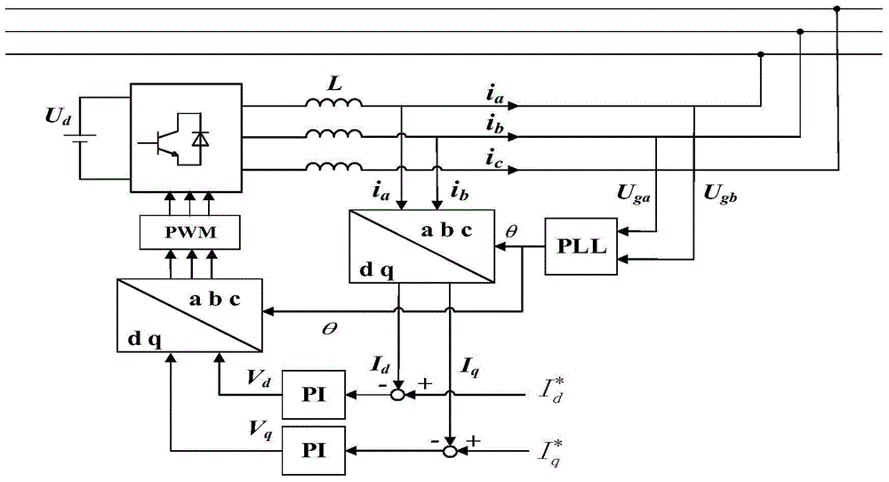
The invention discloses a frequency converter power electronics controllable loading method based on a grid connected inverter. In a present frequency converter test, a dissipating energy type load completely wastes the electricity energy in a test process, and is difficult to accurately simulate load characteristics of the subsidiary engine of the frequency converter. In the method, the output terminal of a frequency converter is directly in connection with a three-phase grid connected inverter to be used as the artificial load of the frequency converter; the main circuit structure successively comprises a front transformer, an uncontrolled rectifier, an intermediate DC capacitor, an inverter, a filter and a rear transformer from front to back; different current given signals are given to the three-phase grid connected inverter to stimulate different load current characteristics; and the three-phase grid connected inverter is controlled by employing the current inner loop strategy based on a PI regulator in a two-phase rotating coordinate system. The method can be used in a high power frequency converter test, and realize reactive power balance control; in a whole process, almost all energy can be fed back to a power grid.

Description

technical field [0001] The invention relates to the technical field of power electronics, in particular to a controllable load method of frequency converter power electronics based on a grid-connected inverter. Background technique [0002] Regardless of the need for technology or energy saving, frequency converters have been widely used in auxiliary machines of steam turbine generator sets in thermal power plants. The fluctuation of the input power supply voltage of the inverter will affect the stable operation of the inverter. In order to improve the high and low voltage ride-through capability of the low-voltage inverter, an additional voltage support device is often used to solve the impact of swaying electricity on the stable operation of the inverter. [0003] In order to check whether the anti-voltage fluctuation level of a type of auxiliary low-voltage inverter itself and the high-voltage and low-voltage ride-through capabilities after the configuration of additional...

Claims


Application Information

Patent Timeline
Patent Type & Authority Applications(China)
IPC IPC(8): G01R31/00
Inventor 吴跨宇蔡慧宣晓华黄晓明楼伯良卢岑岑卢嘉华熊鸿韬沈轶君陆海清马智泉
Owner STATE GRID CORP OF CHINA
Why Eureka
Eureka Blog
Learn More