
A design method of safety interface device for hardware-in-the-loop simulation

A semi-physical simulation and safety interface technology, applied in the field of safety interface devices, can solve the problems of decreased sampling accuracy, equipment accident progress, delay, etc., and achieve the effect of preventing overcurrent flow and reducing the influence of interference

Active Publication Date: 2018-08-14
FUDAN UNIV +1
View PDF6 Cites 0 Cited by
  • Summary
  • Abstract
  • Description
  • Claims
  • Application Information

AI Technical Summary

Problems solved by technology

[0005] 1. Since control boards and hardware-in-the-loop simulators usually use IC chips for logic or digital acquisition of input signals, there are certain restrictions on voltage and current, and overvoltage and overcurrent are generally not allowed
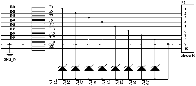
However, simple connector converters only provide direct connection lines without overvoltage and overcurrent protection. Therefore, when there is an overvoltage mistakenly contacting one end or a short circuit fault occurs, it is easy to damage the port of the hardware-in-the-loop simulator, causing equipment accidents and hazards such as delays
[0006] 2. If the digital output of the control board has common-mode interference, or there is a potential difference between the power supply of the control board and the power supply of the emulator, it may cause problems in the digital signal
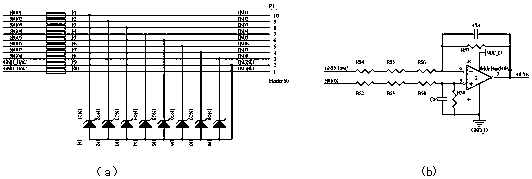
[0007] 3. The voltage range of the analog signal output by the hardware-in-the-loop simulator port is not necessarily the same as the voltage range received by the sampling port of the controller. If one party is accommodated and both output with a smaller voltage range, the sampling accuracy of the other party will decrease, affecting the final Results of Software Evaluation

Method used


Image

  • A design method of safety interface device for hardware-in-the-loop simulation
  • A design method of safety interface device for hardware-in-the-loop simulation
  • A design method of safety interface device for hardware-in-the-loop simulation

Examples


Embodiment 1

[0055] Embodiment 1: the emulator power supply interface voltage maximum value Us is 10V, the photovoltaic system control board power supply interface voltage maximum value Uc is 3V; the control board maximum withstand current Ic is 0.2A, the emulator maximum current Is is 20mA; The transmission frequency fs is 15kHz, the maximum frequency fc of the emulator receiving signal is 125kHz, the maximum communication frequency of the control board is 19.2kHz; the maximum transmission frequency fa of the analog signal is 30kHz, and the maximum frequency far of the emulator sending the analog signal is 125kHz.

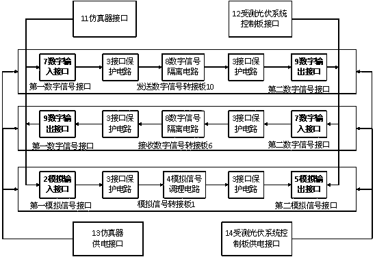
[0056] figure 1 Among them, the emulator interface refers to the interface circuit connected with the hardware-in-the-loop emulator, and the emulator is electrically connected with the present invention by using multi-strand signal lines.

[0057] figure 1 In , the interface of the controller under test refers to the interface circuit connected with the controller board of ...


PUM


Abstract

The invention relates to a safety interface device for semi-physical simulation, and a design method. The device consists of a simulator interface, a tested photovoltaic system control board interface, a simulation signal adapter board, a digital signal receiving adapter board, a digital signal transmitting adapter board, and a peripheral interface power supply part. The device enables a simulator to be connected with a control board interface of a photovoltaic inversion system, can effectively reduce equipment damage risks caused by software and hardware design and connection errors, can make the most of analog precision of the simulator, provides an addition condition of random noise, provides electrical isolation, and reduces risks caused by external static. Meanwhile, aiming at the difference of simulation sampling of a photovoltaic control board, the characteristics of a digital signal and application voltage ranges of a control board and the simulator, the device especially employs a proper amplifier and a proper optical coupler. The device is quick and effect in application, greatly improves work efficiency, and reduces the possibility that misoperation causes loss. The invention provides a simple, convenient and reliable conversion device and design method for the field of semi-physical simulation.

Description

technical field [0001] The invention belongs to the field of semi-physical simulation, and in particular relates to a design method for a safety interface device used for semi-physical simulation. Background technique [0002] With the gradual advancement of the construction of centralized photovoltaic power generation systems and distributed photovoltaic power generation systems, the installed capacity has steadily increased, and the application of photovoltaic inverters has also increased significantly. As one of the devices with the highest technical content in the photovoltaic power generation system, the stability requirements of the photovoltaic inverter in the entire system are becoming more and more stringent. However, due to the constraints of the R&D laboratory environment and hardware conditions, the core controller and control software generally cannot be fully and exhaustively tested before batch application, and there may be risks of being affected by on-site i...

Claims


Application Information

Patent Timeline
Patent Type & Authority Patents(China)
IPC IPC(8): G05B17/02
Inventor 孙耀杰林燕丹吉凡马磊
Owner FUDAN UNIV
Learn More