Reality augmenting system

An augmented reality, semi-transparent and semi-mirror technology, used in stereo systems, optics, instruments, etc., can solve the problems of small viewing angles of augmented reality systems, and achieve the effect of large viewing angles

Inactive Publication Date: 2015-11-18
陈科枫
View PDF13 Cites 20 Cited by
  • Summary
  • Abstract
  • Description
  • Claims
  • Application Information

AI Technical Summary

Problems solved by technology

[0005] Therefore, the technical problem to be solved by the embodiments of the present invention is to overcome the problem of the small viewing angle of the augmented reality system in the prior art, thereby proposing an augmented reality system with an augmented reality function and a large viewing angle

Method used


Image

  • Reality augmenting system
  • Reality augmenting system

Examples


Embodiment 1

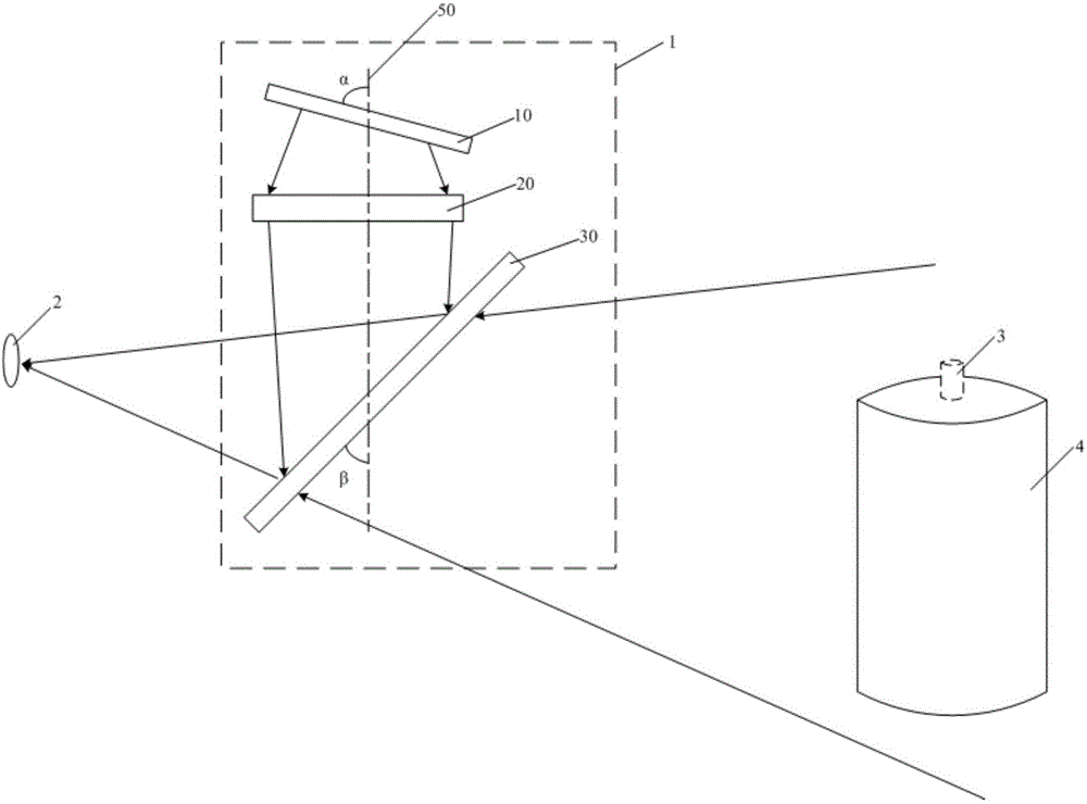
[0044] This embodiment provides an augmented reality system, such as figure 1 As shown, the system 1 includes a display screen 10, an imaging lens group 20, a half mirror 30, a first infrared camera, a second infrared camera and a processor.

[0045]The display screen 10, the imaging lens group 20 and the half-mirror 30 are sequentially arranged along the optical axis 50, the half-mirror 30 forms a certain angle with the optical axis 50, and the light beam route is changed so that the virtual image 3 is located in the field of view of the human eye within range. The human eye observation position 2 is located in front of the half-mirror 30, and the light beam sent by the display screen 10 enters the human eye after being transmitted by the imaging mirror group 20 and reflected by the half-mirror 30, so that the imaging mirror can be observed directly in front of the human eye. Virtual image 3 formed by group 20. Therefore, human eyes can observe the virtual image 3 and the r...

Embodiment approach

[0056] As a preferred embodiment, the system also includes:

[0057] A brainwave sensor for identifying brainwave signals and transmitting them to the processor;

[0058] Gesture recognition sensors for recognizing gesture signals from both hands and transmitting them to the processor;

[0059] The infrared emitting source is used to send out infrared signals to achieve three-dimensional reconstruction of objects.

[0060] non-vocal speech recognition device for recognizing speech signals and transmitting them to said processor;

[0061] The motion sensor is used to identify the motion signal and transmit it to the processor, including a displacement acceleration sensor and an angular acceleration sensor. Preferably, the angular acceleration sensor may be a six-axis gyroscope or the like.

[0062] In this embodiment, by setting brain wave sensors, gesture recognition sensors, infrared emission sources, voice recognition equipment for non-specific human voices, motion sensor...

Embodiment 2

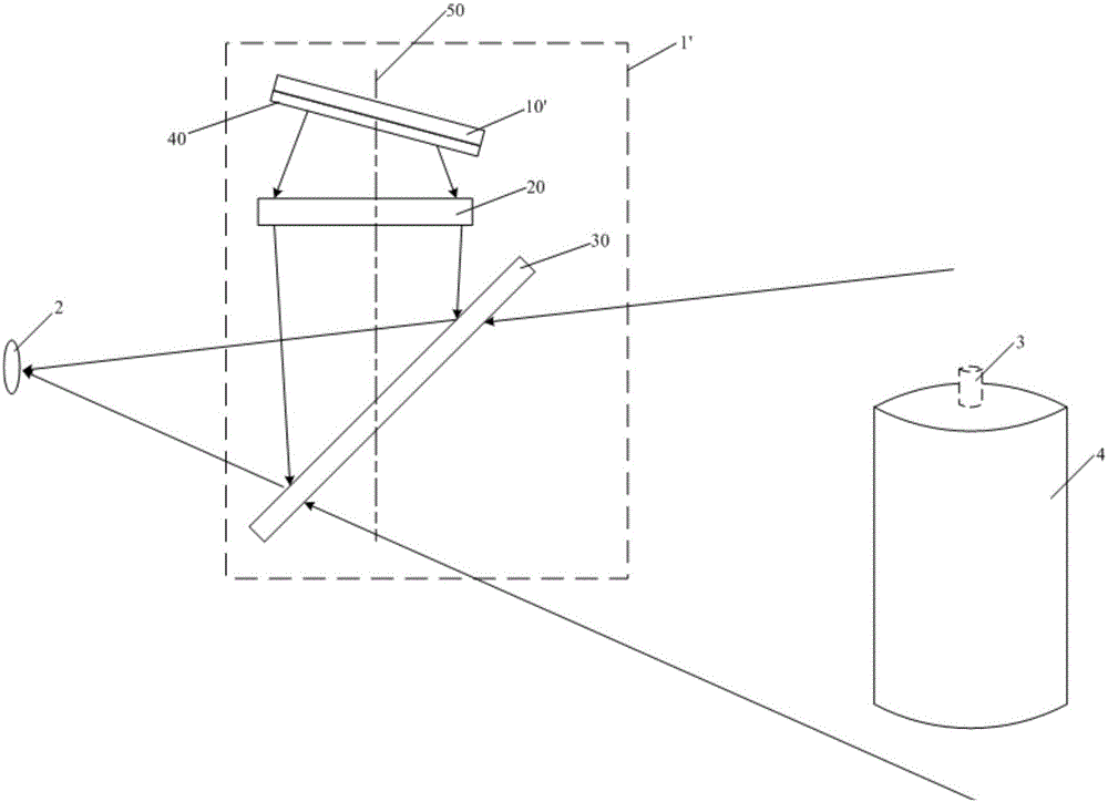
[0064] This embodiment provides an augmented reality system, such as figure 2 As shown, the system 1' includes a display screen 10', a three-dimensional grating 40, an imaging lens group 20, a half mirror 30, a first infrared camera, a second infrared camera and a processor.

[0065] The display screen 10', the three-dimensional grating 40, the imaging mirror group 20 and the half-mirror 30 are sequentially arranged along the optical axis; the three-dimensional grating 40 covers the front of the display screen 10' and is fixedly connected with the display screen 10', and the three-dimensional grating 40 is preferably a lenticular lens grating or a slit grating, and the half mirror 30 forms a certain angle with the optical axis to change the beam route so that the virtual image 3 is located within the field of view of the human eye. The human eye observation position 2 is located in front of the half-mirror 30, and the light beam sent by the display screen 10' is transmitted t...


PUM


Abstract

The invention discloses a reality augmenting system which comprises a display screen, an imaging lens, a half-transparent and half-reflecting mirror, a first infrared camera, a second infrared camera and a processor. The display screen, the imaging lens and the half-transparent and half-reflecting mirror are sequentially arranged along an optical axis, the half-transparent and half-reflecting mirror and the optical axis form a certain angle, the position observed by a human eye is located in front of the half-transparent and half-reflecting mirror, and a light beam emitted by the display screen is transmitted by the imaging lens and reflected by the half-transparent and half-reflecting mirror and then enters the human eye so as to enable a user to observe a virtual image formed by the imaging lens in front of the human eye. The view field of the first infrared camera is similar to the view field which can be observed by the human eye and is used for detecting environment information of the first infrared camera within a view field range and transmitting the environment information to the processor. The second infrared camera is used for capturing a three-dimensional space coordinate of the intersection point of sight lines of the human eye and transmitting the three-dimensional space coordinate to the processor. The reality augmenting system has the advantage of having a large visual angle.

Description

technical field [0001] The invention relates to the technical field of multimedia applications, in particular to an augmented reality system. Background technique [0002] Augmented Reality (AR for short) is a technology that calculates the position and angle of the camera image in real time and adds the corresponding image. The goal of this technology is to put the virtual world on the screen and interact with the real world. This technique was proposed in 1990. With the improvement of the computing power of portable electronic products, the use of augmented reality will become more and more extensive. [0003] The AR system has three outstanding features: ① Information integration between the real world and the virtual world; ② Real-time interactivity; ③ Adding and positioning virtual objects in the three-dimensional scale space. AR technology can be widely used in military, medical, construction, education, engineering, film and television, entertainment and other field...

Claims


Application Information

Patent Timeline
Patent Type & Authority Applications(China)
IPC IPC(8): G06F3/01H04N13/02H04N13/04G02B27/02
Inventor 陈科枫
Owner 陈科枫
Why Eureka
Try Eureka