
Anode saturation reactor of direct-current converter valve

A DC converter valve and reactor technology, applied in the direction of transformer/inductor shell, transformer/inductor cooling, transformer/inductor magnetic core, etc., can solve the complexity of waterway design, complicated waterway and poor heat dissipation effect of iron core And other issues

Active Publication Date: 2015-11-18
NR ELECTRIC CO LTD +2
View PDF14 Cites 7 Cited by
  • Summary
  • Abstract
  • Description
  • Claims
  • Application Information

AI Technical Summary

Problems solved by technology

[0003] The existing anode saturable reactors for DC converter valves mainly have the following methods: Method 1, using a fixed number of coil turns, the logarithm of the iron core is adjustable, and placing the coil and iron core in the saturable reactor for DC converter valves The upper and lower covers are filled with anti-seismic materials. The disadvantage of this method is that the heat dissipation effect of the iron core is poor. Under the premise of meeting the performance requirements, the iron core loss is relatively large.
The second method is formed by coupling a pair of iron cores and coil windings with variable turns. The inductance can be adjusted by adjusting the number of iron cores and the number of turns of the coil. The disadvantage of this method is that the external dimensions of the reactor are difficult to control , and the iron core and coil are cooled by separate water cooling, the water circuit is complex
Method 3: Separately set water-cooled anode saturated reactors for DC converter valves for coils and iron cores. The anode saturated reactors for DC converter valves have good performance in heat dissipation, shock resistance, and noise reduction. Increased core water-cooling branch, resulting in the complexity of waterway design and the possibility of waterway blockage and water leakage

Method used


Image

  • Anode saturation reactor of direct-current converter valve
  • Anode saturation reactor of direct-current converter valve
  • Anode saturation reactor of direct-current converter valve

Examples


Embodiment

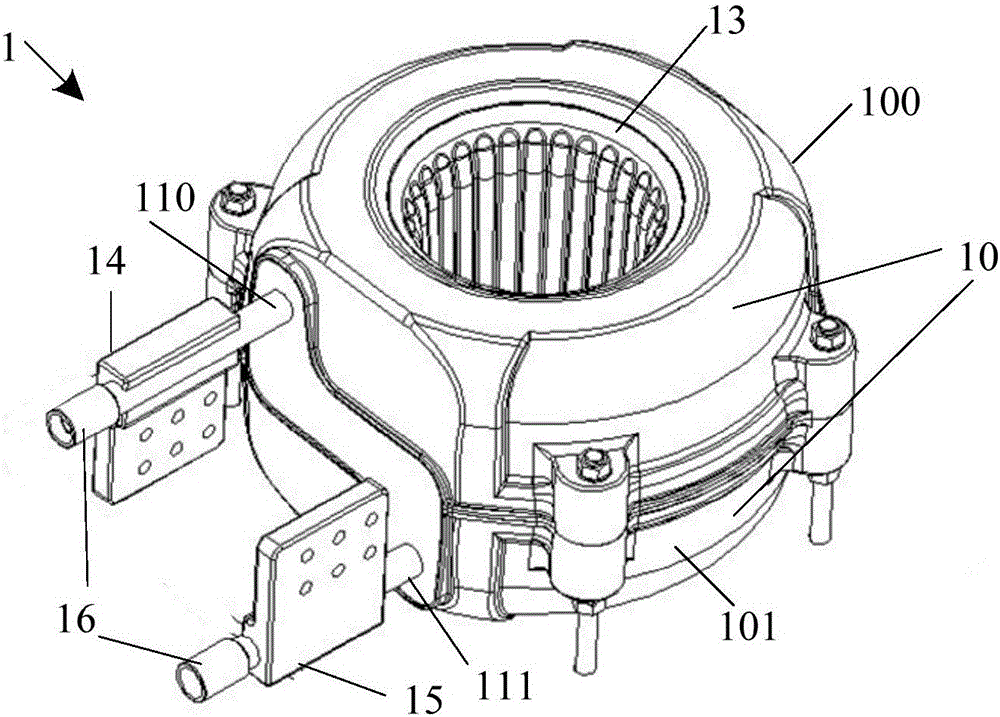
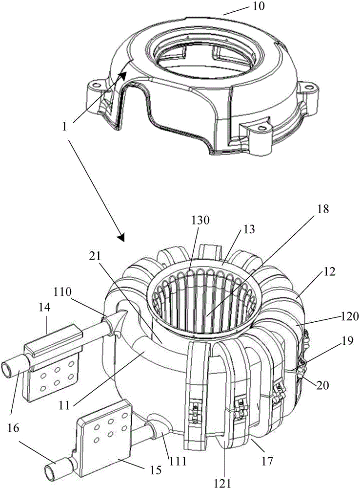
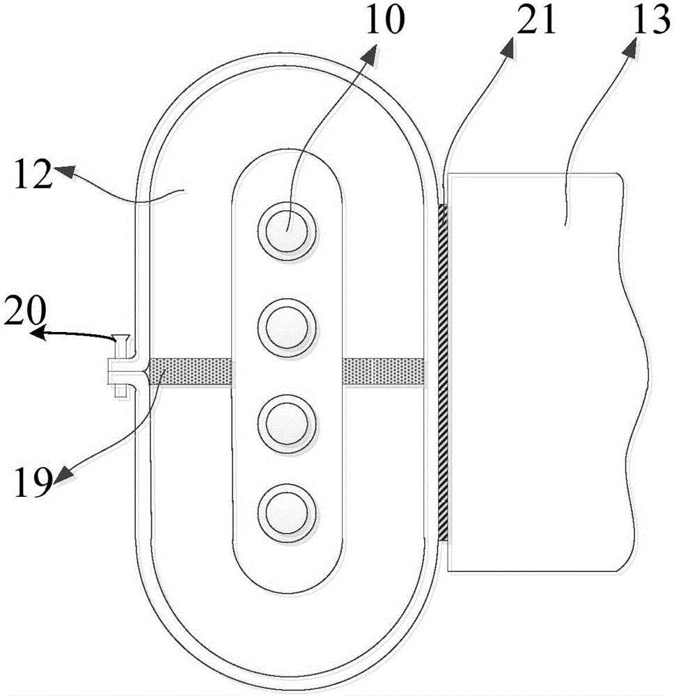
[0029] Exemplary combination figure 1 , figure 2 and image 3 It can be seen that the embodiment of the present invention provides an anode saturated reactor 1 for a DC converter valve, and the anode saturated reactor 1 for a DC converter valve includes: a casing 10, a set of coils 11, at least a pair of iron cores 12 and an iron core Radiator 13; each iron core 12 includes a first iron core part 120 and a second iron core part 121, and the first iron core part 120 and the second iron core part 121 are U-shaped structures up and down or C-shaped left and right structure.

[0030] The at least one pair of iron cores 12 is fastened in pairs between the inner and outer walls of the group of coils 11 to form a closed coupling.

[0031] The at least one pair of iron cores 12 is arranged along the circumferential direction of the group of coils 11 .

[0032] The core radiator 13 is arranged inside the inner wall of the group of coils 11, contacts with the at least one pair of c...


PUM


Abstract

The embodiment of the invention discloses an anode saturation reactor of a direct-current converter valve. The anode saturation reactor comprises a shell, a coil, at least one pair of iron cores and an iron core heat dissipater. Each iron core comprises a first iron core part and a second iron core part which are of an upper and lower U-type structure or a left and right C-type structure; the iron cores are buckled between the inner wall and the outer wall of the coil to form closed coupling; the iron cores are arranged in the circumferential direction of the coil; the iron core heat dissipater is arranged in the inner wall of the coil and makes contact with the iron cores; the iron core heat dissipater is exposed in air and is in butt joint with the shell.

Description

technical field [0001] The invention relates to reactor technology in the field of power system components, in particular to an anode saturated reactor of a DC converter valve. Background technique [0002] Saturable reactors for DC converter valves are key components of thyristor converter valves in UHVDC transmission projects. It also plays a pressure equalizing role on the converter valve, and has achieved the purpose of protecting the converter valve. [0003] The existing anode saturable reactors for DC converter valves mainly have the following methods: Method 1, using a fixed number of coil turns, the logarithm of the iron core is adjustable, and placing the coil and iron core in the saturable reactor for DC converter valves The upper and lower covers are filled with anti-seismic materials. The disadvantage of this method is that the heat dissipation effect of the iron core is poor, and the core loss is relatively large under the premise of meeting the performance re...

Claims


Application Information

Patent Timeline
IPC IPC(8): H01F27/24H01F27/08H01F27/28H01F27/29H01F27/02H02M1/00
Inventor 张翔方太勋封怀荣杨帆刘磊陈赤汉杨兰筠谷海涛
Owner NR ELECTRIC CO LTD
Learn More