Eureka AIR delivers breakthrough ideas for toughest innovation challenges, trusted by R&D personnel around the world.

UWB antenna compatible with wlan system

A technology of ultra-wideband antenna and microstrip feeder, which is applied to antennas, devices that enable antennas to work in different bands at the same time, and the structural form of radiation elements, etc., can solve problems such as spectrum congestion and immature technical means of ultra-wideband antennas, and achieve a solution Spectrum Crowded, Light Weight, Low Cost Effects

Active Publication Date: 2018-03-13
HARBIN INST OF TECH
View PDF4 Cites 0 Cited by
  • Summary
  • Abstract
  • Description
  • Claims
  • Application Information

AI Technical Summary

Problems solved by technology

[0004] The purpose of the present invention is to propose an ultra-wideband antenna compatible with WLAN systems in order to solve the problem that the existing ultra-wideband antenna technology is not mature enough and there is spectrum congestion

Method used


Image

  • UWB antenna compatible with wlan system
  • UWB antenna compatible with wlan system
  • UWB antenna compatible with wlan system

Examples


specific Embodiment approach 1

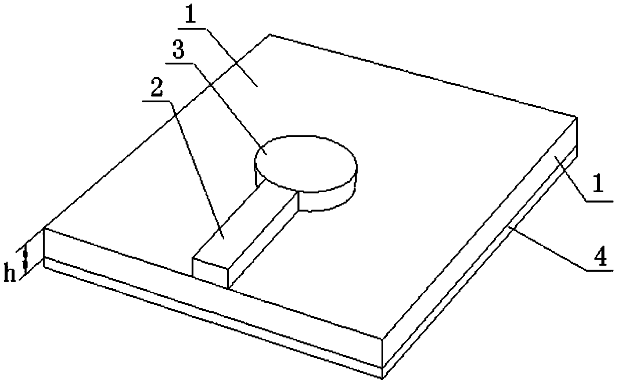
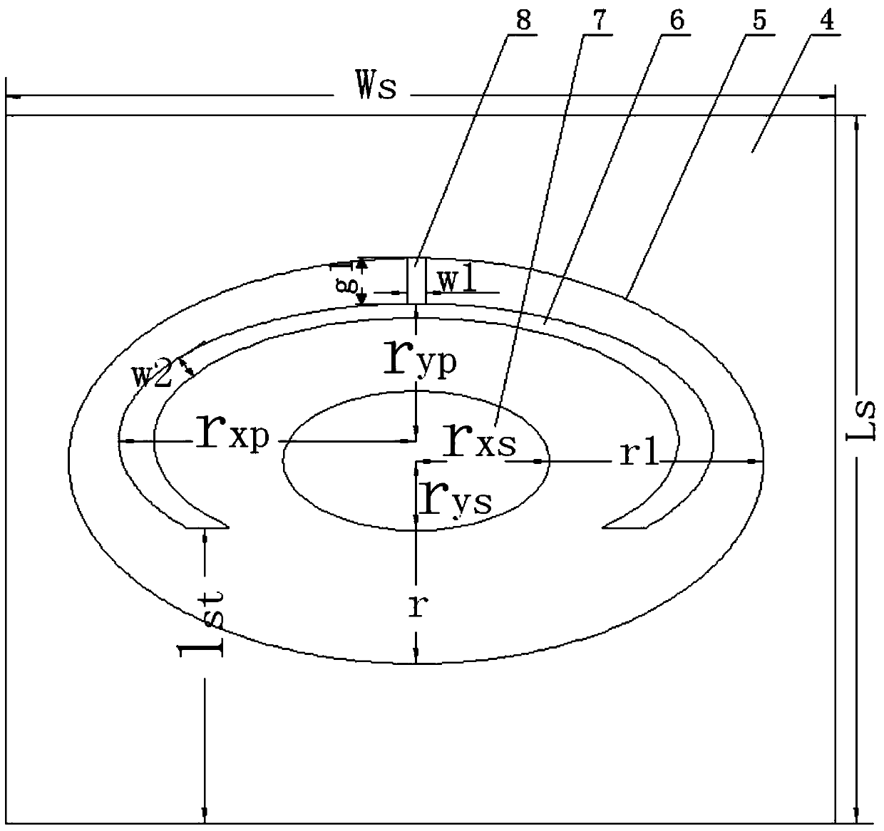
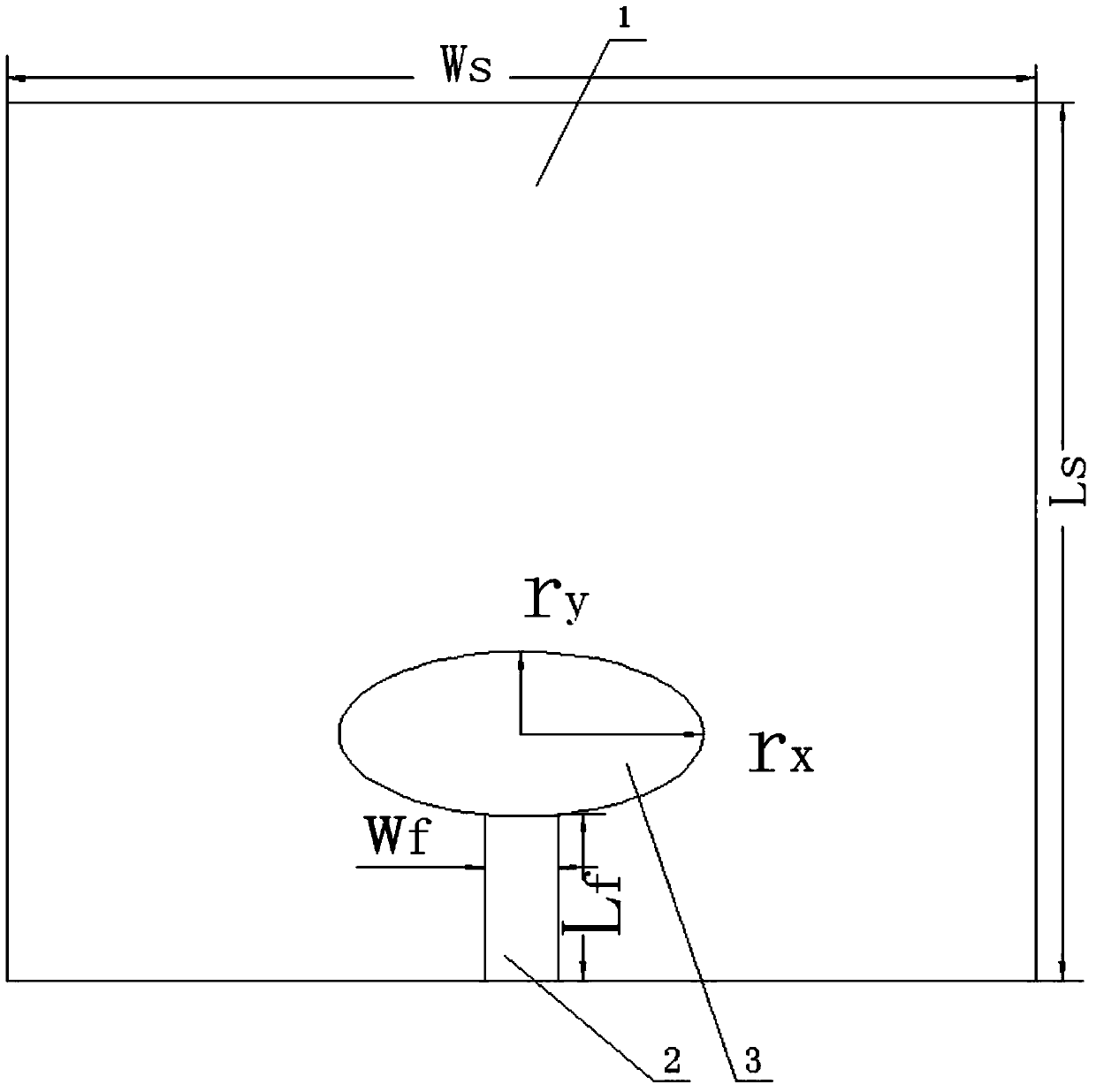
[0012] The ultra-wideband antenna compatible with the WLAN system in this embodiment, combined with figure 1 As shown, the ultra-wideband antenna includes: a dielectric substrate 1, a microstrip feeder 2 and an elliptical adjustment branch 3 are printed on the side panel of the dielectric substrate 1, and one end of the microstrip feeder 2 extends to the short axis of the ellipse adjustment branch 3 The other end extends to the edge of the dielectric substrate 1; the other side of the dielectric substrate 1 is printed with a metal patch 4, and the center of the metal patch 4 is provided with an elliptical hole 5 to achieve the purpose of ultra-wideband, and the inside of the elliptical hole 5 is surrounded by The microstrip adjustment branch 6 and the elliptical metal patch 7 are printed sequentially toward the center to expand the bandwidth of the high-frequency band of the antenna, and the low-frequency band of the antenna is adjusted through the elliptical microstrip branch ...

specific Embodiment approach 2

[0013] The difference from Embodiment 1 is that, in the ultra-broadband antenna compatible with the WLAN system in this embodiment, the microstrip adjusting branch 6 is strip-shaped and surrounded by an ellipse with a gap.

specific Embodiment approach 3

[0014] The difference from Embodiment 1 or Embodiment 2 is that in the ultra-wideband antenna compatible with the WLAN system in this embodiment, the oval hole 5 is set at the center of the metal patch 4 .


PUM


Abstract

An ultra-wideband antenna compatible with a WLAN system belongs to the field of wireless communication. The existing ultra-wideband antenna technology is not mature enough, and there is a problem of spectrum congestion. An ultra-wideband antenna compatible with a WLAN system, the ultra-wideband antenna comprising: a microstrip feeder (2) and an elliptical adjustment branch (3) printed on one side panel of a dielectric substrate (1); the other side of the dielectric substrate (1) A metal patch (4) with an elliptical hole (5) is printed on the side panel, and the inside of the elliptical hole (5) is printed with a microstrip adjustment branch (6) and an elliptical metal patch (7) from outside to inside. A metal connecting bridge (8) is also arranged between the edge and the outer edge of the microstrip adjusting branch (6). The antenna of the invention realizes the compatibility between the ultra-wideband antenna and the WLAN system, and the wide high-frequency band can fully solve the spectrum congestion problem, and has the advantages of low profile, compact structure, light weight, low cost and easy integration.

Description

technical field [0001] The invention relates to an ultra-wideband antenna compatible with a WLAN system. Background technique [0002] Ultra-wideband antennas can realize communication, radar, navigation and electronic warfare transmission and reception at the same time, greatly reduce the volume and load of the antenna system, realize the optimal layout of the antenna system on the carrier, and effectively reduce the radar cross section of the antenna system. The high point of technology. In recent years, with the opening of commercial applications of ultra-wideband technology teams, more and more ultra-wideband antennas are used in wireless communication systems, which has become a new research hotspot. [0003] However, the technical means of ultra-wideband antennas are not yet mature enough, and there is a problem of spectrum congestion. Contents of the invention [0004] The object of the present invention is to propose an ultra-wideband antenna compatible with a WL...

Claims


Application Information

Patent Timeline
Patent Type & Authority Patents(China)
IPC IPC(8): H01Q1/38H01Q5/25
Inventor 陈立甲李国际许琳李浩
Owner HARBIN INST OF TECH
Why Eureka
Eureka Blog
Learn More