
Microwave energy receiving plate

A technology of energy reception and microwave, applied in the direction of electromagnetic wave system, etc., can solve the problems of low energy conversion efficiency and lower energy utilization rate, and achieve the effects of variable structure, improved efficiency, and uniform effective aperture

Inactive Publication Date: 2015-11-18
ZIGONG INNOVATION CENT OF ZHEJIANG UNIV
View PDF3 Cites 5 Cited by
  • Summary
  • Abstract
  • Description
  • Claims
  • Application Information

AI Technical Summary

Problems solved by technology

In addition, some project groups have studied rectenna arrays in an attempt to increase the received energy, but compared with the receiving efficiency of a single unit antenna, the overall energy conversion efficiency is lower, and due to consideration of size and volume factors, rectenna arrays require a more compact design , but due to the coupling between ordinary antenna elements, the distance between the array elements is at least half a wavelength, which greatly reduces the energy utilization rate

Method used


Image

  • Microwave energy receiving plate
  • Microwave energy receiving plate
  • Microwave energy receiving plate

Examples


specific Embodiment 1

[0046] This specific embodiment is described by taking a microwave energy receiving board with a structural working frequency of 5.8 GHz, that is, a working wavelength of about 50 mm, as an example.

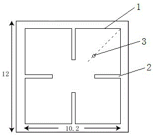
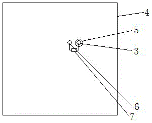
[0047] In this specific embodiment, the microwave energy receiving plate is constituted by a single sub-wavelength resonant structural unit. Such as figure 1 and figure 2 As shown, the sub-wavelength resonant structure unit is a square structure, including a sub-wavelength resonant structure and a high-frequency rectifier circuit connected to it; the high-frequency rectifier circuit includes a high-frequency rectifier chip and its auxiliary circuit; the sub-wavelength resonant structure including from top to bottom,

[0048] The top metal layer 1 is a square structure, and the middle position of each side is provided with a strip-shaped gap 2 extending to the center of the top metal layer, a total of four strip-shaped gaps; the width of the four strip-shaped gaps is equal; Th...

specific Embodiment 2

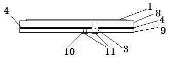
[0056] Such as image 3 As shown, similar to the specific embodiment 1, the difference is that the sub-wavelength resonant structural unit also includes an underlying insulating dielectric layer 9, and two through holes are arranged on the underlying insulating dielectric layer, one of which is connected to the positive input Corresponding to the through hole 3, the other through hole 10 is connected to the ground metal layer; two pads 11 are provided at the bottom of the bottom insulating dielectric layer, and each of the two through holes corresponds to a pad, and the high frequency rectifier through the pad The positive and negative poles of the diode are connected. Such a structure facilitates the formation of a large-area and high-efficiency microwave energy receiving plate by multiple sub-wavelength resonant structural units. In this specific embodiment, the thickness of the underlying insulating dielectric layer is 0.5 mm; the thickness of the pad is 0.035 mm.

specific Embodiment 3

[0057] Such as Figures 4 to 6 As shown, the difference from Embodiment 2 is that in this embodiment, the microwave energy receiving plate is composed of multiple sub-wavelength resonant structural units described in Embodiment 2. For each structural unit, the top metal layer The size of is smaller than the size of the whole structural unit. . Many sub-wavelength resonant structural units are periodically arranged to form a receiving board. When working, the rectifier chips on each unit will convert the radio frequency AC signals absorbed by them into DC voltages, and connect the DC voltages output by multiple units in series. The DC power supply generated by the unit is connected in series to generate a DC power supply of the required voltage to realize a high-efficiency microwave energy receiving board. When the high-efficiency wireless energy receiving board is working, the circularly polarized electromagnetic waves incident on the sub-wavelength resonant structure will g...


PUM


Abstract

The invention provides a microwave energy receiving plate. The microwave energy receiving plate includes sub-wavelength resonant structure units of square structures; each sub-wavelength resonant structure unit comprises a sub-wavelength resonant structure and a high-frequency rectification circuit connected with the sub-wavelength resonant structure; the sub-wavelength resonant structure includes a top-layer metal layer, an insulating supporting stratum layer and a grounding metal layer; the top-layer metal layer is of a square structure; an elongated gap which extends towards the center of the top-layer metal layer is formed at the middle position of each side of the square structure of the top-layer metal layer respectively, so that altogether four elongated gaps are provided; the widths of the four elongated gaps are equal; every two opposite elongated gaps of which the lengths are equal form one group of elongated gaps; and the length of one group of elongated gaps is larger than the length of the other group of elongated gaps. With the microwave energy receiving plate adopted, perfect matching between a space environment and the rectification circuits can be realized. The structures of the plurality of units are compact, so that the microwave energy receiving plate can be equivalent to a perfect homogeneous-medium energy receiving plate, and the overall receiving efficiency of the microwave energy receiving plate is more than 90%.

Description

technical field [0001] The invention relates to the field of wireless energy receiving, in particular to a circularly polarized microwave energy receiving board formed by sub-wavelength resonance units. Background technique [0002] Microwave energy transmission technology refers to a non-contact microwave energy transmission technology that uses free space as the propagation medium to directly transmit energy from the transmitting end to the receiving end. Because the transmission efficiency of microwave energy transmission technology in the S-band and C-band is generally 90 %, and the intensity and direction of microwave beams are easier to control, making microwave energy transmission technology receive more and more attention internationally and domestically, especially in recent years, it has been fully developed, in radar systems and wireless microwave energy There are broad application prospects in transmission. [0003] Since Tesla's experiments at the end of the se...

Claims


Application Information

Patent Timeline
Patent Type & Authority Applications(China)
IPC IPC(8): H02J17/00
Inventor 叶德信杨彦彬冉立新
Owner ZIGONG INNOVATION CENT OF ZHEJIANG UNIV
Learn More