Method for controlling dynamic response of switch power

A technology of switching power supply and control method, applied in the direction of program control, general control system, control/regulation system, etc., can solve the problems of reduced dynamic effect, voltage drop, slow dynamic process, etc., to reduce dynamic recovery time and dynamic recovery. Time reduction, avoidance of voltage resonance effects

Active Publication Date: 2015-11-18
SOUTHEAST UNIV
View PDF6 Cites 23 Cited by
  • Summary
  • Abstract
  • Description
  • Claims
  • Application Information

AI Technical Summary

Problems solved by technology

If the load is on standby, according to the size of the dummy load, assuming that the standby frequency is 2kHz, the control mode is DPFM mode at this time, if the load suddenly changes to full load, the output voltage drops at a fast speed, and the control mode will be different according to the compensation result After DPWM, PFM, and PWM modes, when the compensation result does not reach the full-load condition, the output voltage is always dropping, which may cause a serious voltage drop, which is unbearable under some conditions; the same is true when switching from full load to light When the load is applied, the middle mode control process will cause the voltage to rise continuously, and the voltage will produce a large overshoot
In addition, in some conditions, in order to prevent mode switching, the control mode switches back and forth between the two modes near the switching point, and it takes several cycles to confirm the need to switch mode control from one mode to another. Under such conditions, the dynamic effect will be further reduced
[0004] In addition, in some controls, it can only be sampled once in a cycle, for example, in a flyback power supply with primary side feedback, the output voltage can only be sampled before the secondary current drops to zero
In this way, when the load changes from light to heavy, the switching frequency of DPWM is low, even if the PI adjustment is large, but in order to ensure stability, the dynamic process is slower
[0005] In addition, in order to speed up the dynamic response, some control methods will increase the PI parameter to speed up the compensation, so as to improve the dynamic effect, but the effect of multi-mode control on improving the dynamic performance is not much improved.

Method used


Image

  • Method for controlling dynamic response of switch power
  • Method for controlling dynamic response of switch power
  • Method for controlling dynamic response of switch power

Examples


Embodiment Construction

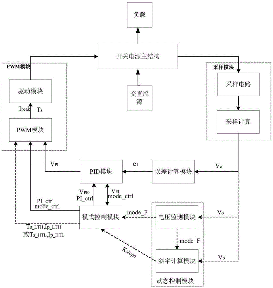
[0036] Referring to FIG. 1 , the solid line arrows are the signal flow used by the control loop in the normal working mode, and the dotted line arrows and solid line arrows are the signal flow in the control loop in the dynamic mode.

[0037] The control method for improving the dynamic response of the switching power supply in the present invention is based on a control system composed of a sampling module, a dynamic control module, an error calculation module, a PID module, a mode control module and a PWM module, and the control system is connected with a controlled switching power supply to form a a closed loop;

[0038] The sampling circuit in the sampling module samples the output voltage of the switching power supply, and the output voltage information is input to the sampling calculation module. The sampling calculation module obtains the signal Vo of the output voltage according to the sampling algorithm, and inputs the current sampling voltage Vo to the dynamic control...


PUM


Abstract

A method for controlling dynamic response of switch power is based on a closed-loop control system including a sampling module, a dynamic control module, an error calculating module, a PID module, a mode control module and a PWM module, wherein the sampling module samples output voltage Vo, and the dynamic control module compares the Vo with set Vo max, Vo min and V ref. Whether a dynamic mode is employed is determined. When the output voltage Vo changes greatly under the dynamic mode, the voltage Vo is rapidly restored to a stable voltage by inputting large power or small power, and the load is detected by voltage change gradient to determine the working state and reduce voltage resonance. The dynamic response effect is improved.

Description

technical field [0001] The invention relates to a switching power supply, in particular to a control method for improving the dynamic response of the switching power supply. Background technique [0002] Switching power supplies are usually used as power supplies for various types of electrical equipment to convert unadjusted AC or DC input voltages into adjusted AC or DC output voltages. Since the switching power supply needs to adapt to different working conditions, the performance requirements for the dynamic response of the power supply are getting higher and higher. Good dynamic effects require small voltage changes and voltage recovery times. For example, in the application of home appliances, the load power of the power supply of the washing machine changes rapidly and greatly, so that the output voltage of the power supply introduces overvoltage and undervoltage, and when the overvoltage and undervoltage are too large, the load of the washing machine power supply is...

Claims


Application Information

Patent Timeline
Patent Type & Authority Applications(China)
IPC IPC(8): H02M1/08H02M3/335
CPCH02M3/33515H02M3/33523G05B19/042G05B2219/2639H02M1/0019H02M1/0025Y02B70/10H02M1/0048H02M1/08
Inventor 徐申王冲范献军孙伟锋陆生礼时龙兴
Owner SOUTHEAST UNIV
Why Eureka
Try Eureka