Delay-locked loop adopting novel error lock detection circuit

A delay-locked loop and lock detection technology, applied in the field of delay-locked loops, can solve small lock-in errors, errors, etc., and achieve the effect of eliminating harmonic lock-in and high lock-in accuracy

Inactive Publication Date: 2015-11-18
SOUTHEAST UNIV
View PDF5 Cites 10 Cited by
  • Summary
  • Abstract
  • Description
  • Claims
  • Application Information

AI Technical Summary

Problems solved by technology

[0005] Purpose of the invention: In order to overcome the deficiencies in the prior art, the present invention provides a delay-locked loop using a new type of error-l

Method used


Image

  • Delay-locked loop adopting novel error lock detection circuit
  • Delay-locked loop adopting novel error lock detection circuit
  • Delay-locked loop adopting novel error lock detection circuit

Examples


Embodiment Construction

[0018] The present invention will be further described below in conjunction with the accompanying drawings.

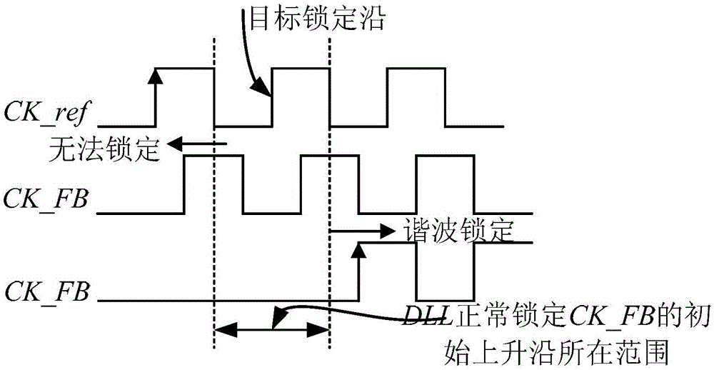
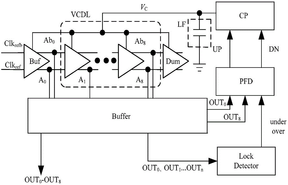
[0019] A system block diagram of a delay-locked loop using a new type of error lock detection circuit is shown in image 3 , its working timing diagram is as follows Figure 4 ; The delay-locked loop includes an error lock detection circuit, a phase detector, a charge pump, a low-pass filter and a voltage-controlled delay line, and the voltage-controlled delay line includes a differential to single-ended conversion circuit, and the voltage-controlled delay line VCDL converts the phase clock signal out 0 ~OUT 6 Input error lock detection circuit, the 0th phase clock signal OUT 0 As the reference clock input phase detector of the phase detector PFD, the last stage phase clock OUT 8 As a feedback clock input phase detector; the error lock detection circuit is used according to the input phase clock signal OUT 0 ~OUT 6 Output the under signal or over signal to the ch...


PUM


Abstract

The invention discloses a delay-locked loop adopting a novel error lock detection circuit, comprising the error lock detection circuit, a phase detector, a charge pump, a low pass filter and a voltage control delay line. The error lock detection circuit detects all output phase clocks of the voltage control delay line, inputs a detection signal into the phase detector, and outputs a charge-discharge control signal to the charge pump. Through adoption of the delay-locked loop, the problem of harmonic wave locking of the conventional delay-locked loop in a broadband range is solved, the harmonic wave locking is eliminated, and a multiphase output of fixed time delay is provided.

Description

technical field [0001] The invention relates to a clock signal generation circuit, in particular to a delay-locked loop adopting a novel error lock detection circuit. Background technique [0002] With the continuous increase of the amount of data processed by integrated circuit chips per unit time, the speed of signal processing inside the chip is required to increase accordingly, that is, the clock frequency needs to be continuously increased. Therefore, as the key core module clock circuit in digital integrated circuit chips, its own Performance indicators directly affect the realization of overall chip performance. In order to meet the needs of users for the diversification of chip functions, more and more module circuits are integrated on the same chip for the sake of cost reduction. Due to the limitation of PCB cost and technology, it is difficult for the off-chip clock to generate the required higher frequency clock for the chip, so it is inevitable to design the clo...

Claims


Application Information

Patent Timeline
IPC IPC(8): H03L7/08H03L7/085
Inventor 吴金张有志江琦李文波赵荣琦郑丽霞孙伟锋
Owner SOUTHEAST UNIV
Why Eureka
Try Eureka