Purification method and device for filling machine

A technology of purification device and filling machine, which is applied to chemical instruments and methods, cleaning methods using liquids, cleaning of filling devices, etc., can solve the problems of reduced productivity of beverage filling containers, downtime (longer production downtime, etc.) The effect of shortening production downtime, preventing poor cleaning, and improving production efficiency

Active Publication Date: 2017-05-17
DAI NIPPON PRINTING CO LTD
View PDF10 Cites 0 Cited by
  • Summary
  • Abstract
  • Description
  • Claims
  • Application Information

AI Technical Summary

Problems solved by technology

[0020] However, if COP and SOP are performed in the aseptic chamber after waiting for the completion of CIP and SIP of the piping for the beverage supply system, the downtime (production stop time) of the filling machine and the aseptic filling device as a whole will become longer, and the beverage filling container Reduced productivity

Method used


Image

  • Purification method and device for filling machine

Examples


Embodiment Construction

[0043] Hereinafter, embodiments of the present invention will be described with reference to the drawings.

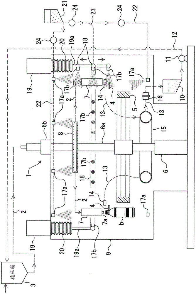
[0044]In the aseptic filling device, there is a brewing tank not shown in the beverage to figure 1 The shown filling machine 1 supplies a beverage supply line 2 with a beverage. exist figure 1 In , reference numeral 3 denotes a surge tank provided in the middle of the piping of the beverage supply system.

[0045] In addition, the aseptic filling device is provided with a bottle conveying path for conveying the bottle b, which is a container filled with beverage, to the filling machine 1, and conveying the bottle b filled with the beverage by the filling machine 1 to a capping machine not shown. The conveyance path is usually formed by combining a plurality of gears in a row. Furthermore, tongs 4 and the like are arranged at regular intervals around the respective wheels.

[0046] The filling machine 1 is a filling machine that fills beverages into a plurality of bo...


PUM


Abstract

A method and device for purifying a filling machine, which performs COP and One or both of the SOPs, when executing one or both of the COP and the SOP, make at least the movable spray nozzle (17b) opposite to the filling machine (1) from the outer periphery of the filling machine (1) in the filling machine (1) The up and down direction reciprocates, and the prescribed working fluid is sprayed to the outside of the filling machine (1) in a prescribed order, thereby purifying the filling machine. Thereby, the downtime of the beverage filling operation is shortened.

Description

technical field [0001] The present invention relates to a method and an apparatus for purifying a filling machine for filling beverages into containers such as bottles while rotating a plurality of filling nozzles by cleaning and sterilizing. Background technique [0002] A filling machine that fills a plurality of bottles with beverages at high speed has a plurality of filling nozzles arranged at regular intervals along a circumference in a predetermined horizontal plane. Since this filling machine fills the aseptically processed beverage so that foreign substances such as microorganisms do not enter the aseptically processed bottle, the entirety is accommodated in the aseptic chamber. [0003] When filling the beverage, all the filling nozzles of the filling machine rotate at a high speed together and inject a certain amount of beverage into the bottles coming at the same time. As mentioned above, since the filling machine is housed in the aseptic chamber, filling of the ...

Claims


Application Information

Patent Timeline
Patent Type & Authority Patents(China)
IPC IPC(8): B67C3/00
CPCB08B3/02B67C3/001B67C3/005
Inventor 早川睦桑野诚司
Owner DAI NIPPON PRINTING CO LTD
Why Eureka
Try Eureka